Appendix 3 Wiring Diagram 27
NetSure 531 A41, NetSure 531 A91 Subrack Power system User Manual
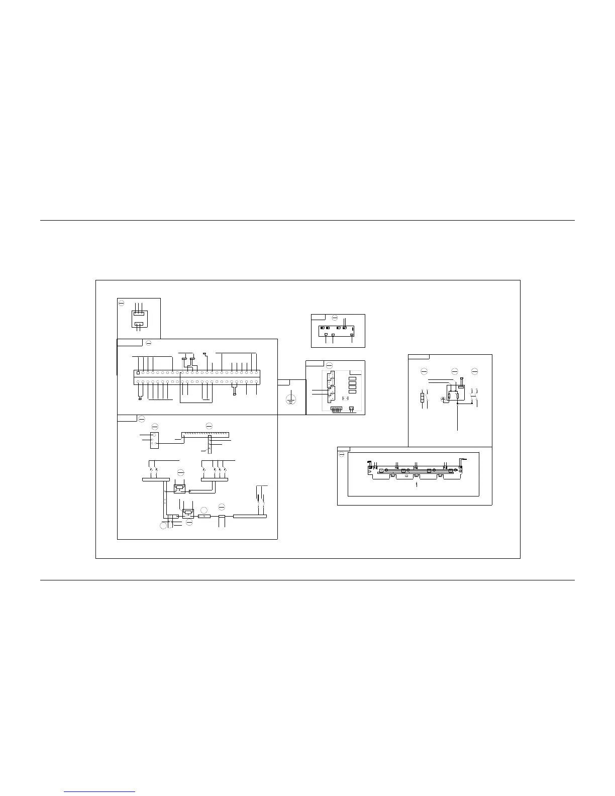
Appendix 3 Wiring Diagram
MFU DC wiring diagram
MFU
8
Rear top view
13
W2453X1
W2453X1
J6
21
J3
1+
1-
2+
2-
Front view
J8
1
8
W80
J7
1 2
1
2
3
4
5
6
7
8
9
10
11
12
13
14
15
16
17
18
19
20
21
22
23
24
25
26
27
28
29
30
31
32
33
34
35
36
37
38
39
40
41
42
43
44
45
46
47
48
49
50
13-J8-1
24-CAN-
M221S
7
18-J1-1
11-2
11-1
24-CAN+
13-J7-1
13-J7-2
X10-2
13-J8-2
13-J8-3
13-J8-5
13-J8-4
13-J8-6
13-J8-7
13-J8-8
8-QFB2-1
8-QFB1-1
10-2
10-1
W80
W80
W84
W84
W80
W80
W80
W80
W80
W80
X3-2
W809-BUS+-2
X6-1 X5-1
8-PL-1
W80
9-BUS+-1
W80
W80
8-PL-1
18
M34C3C1
18-J1-2
8-PL-2
W06
5-2
W80
Shelf 1
6
Subrack
J6
J3
15
M2433X2
J7J5
J1
J2
J4
v-
v+
PE
W06
9-2
W06
J4
3+
3-
4+
4-
DO3
DO4
DO1
DO2
DCSPD
13-J3-1+
13-J3-1-
15-J4-1
15-J4-2
W06
W06
W06
TO the protection earth of the users
1
2
3
5-3
W07
2
1
1
2
PL
1
2
1
2
7-30
QFB1
QFB2
7-28
7-20
7-22
18-J2-1
18-J2-2
W80
15-J5
W06
1
2
7-45
7-43
NPL
8-B-
1
2
1
2
QFD1
QFD2
1
2
QFD3
1
2
QFD4
NPL
1
2
1
2
QFD5
QFD6
PL
0V
To the positve busbar of the module
PE
5
TO the negative busbar of the module
1
BUS+
9
RB
10
KM1
11
KM2
12
2
9-2
1
W80+W81+W82
7-29
7-29
W84
W80
W80
W84
W80
W80
7-35/7-47/7-49/7-50
9-BUS+-3
15-J6
W06
12-1
W84
4
2
W809-BUS+-1
3
X5-1/X6-1
W80
8-QFD
Single-phase AC input
Front view
1
2
15-J7
W80
W06
7-31/7-46
18-J2-3
W84
W80+W81+W82
Front top view (open the panel)
2
J2
1
2
3
J1
1
7-39
7-41
12-1
12-2
8-PL-1
W84
W84
2
1
to M221S /M222S
H5
DC-
DC-
L N
L N
L N
L N
J2
J1
J4J3
H2
H1
J13
J11
H3 H4
DC+
U1 U2
DC+DC-
J12 U3
DC+
U4
DC+DC-
J14
U11 U12 U13 U14
DC-
DC+
1-2
1-4
31
W2493ZX 1
1-4
1-4
1-4
1-2
J41
CAN+
CAN-
J42
CAN+
CAN-
7-4
7-2
W02
W1 W1 W1 W1
X3-1
Front top view of the back plat(with the contorller and rectifier)
1-2
1-2
2
1
W02
W07
8-PL
QFA
1
SPD1
2
QFA2
3
L1
1 3
2 4
N
L
N-1
PE
1
2
N L
2-L
3
4
W01W01
COM
NC
NO
W01
X10-1
7-42
7-40
W01
W01
2-N-2
31-J1-L/31-J2-L/31-J3-L/31-J4-L/3-2
2-N-2
W01
W01
N-2
31-J1-1/31-J2-1/32-J3-1/32-J4-1
3-4/1-4
Description
:
1. Connected the X10-1 to the X10-2, connected X3-1 to the X3-2.
2. Connected the X5-1 and the X6-1 to the cable of the
temperature sensor for system configuration.
User interface
board 1
Door connected
ground
with the SPD
Controller busbar socket

 Loading...


