Chapter 2 Installation Instruction 9
NetSure 531 A41, NetSure 531 A91 Subrack Power system User Manual
Note
1. If the AC input of the subrack is selected as terminal by user, there is no overcurrent and short circuit protection, and you
should configure the overcurrent and short circuit protection in the previous level of the subrack. Please contact Vertiv Tech Ltd
of local technical support for the device options.
2. Recommends that tightening torque of the users grounding screw is 10.78N*M.
3. If AC input of the system configured with SPD is single-phase, unplug the alarm terminal of the SPD before connecting the
ground wire. Then connect the ground wire, and finally reinstall the alarm terminal of the SPD.
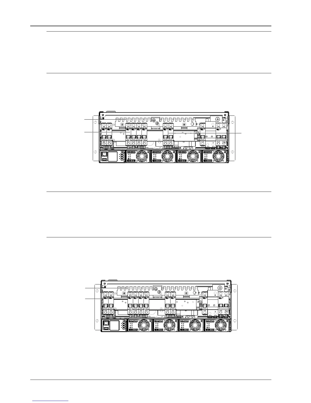
2.4.3 Connecting Load Cables
Connect the negative cable of the load to the upper terminal of load MCB. Connect the positive cable of the load to
the DC positive busbar, as shown in Figure 2-11.
Positive terminal
Load MCB
Figure 2-11 Illustration of the load cable connection terminal
2.4.4 Connecting Battery Cables
Note
The batteries may have dangerous current. When connecting the battery cables, observe the following rules:
1. Make sure all the battery MCBs are disconnected.
2. Make sure that the battery cables and the battery string are disconnected. You can also disconnect the battery cell connector to
avoid live state or short circuit to the chassis of the power system after installation.
3. Be careful not to reverse connect the battery. Otherwise, both the battery and the power system will be damaged!
4. Never remove the battery cables at the top of the battery MCB when the battery input port of the power system is in live state.
1. Connect one end of the negative battery cable to the upper terminal of battery MCBs. Connect one end of the
positive battery cable to the DC positive bus bar.
2. Connect copper lugs to the other end of the battery cables. Bind the connecting parts with insulating tape, and put
them beside the battery. Connect the cables to the battery when the DC distribution unit is to be tested. As shown in
Figure 2-12.
Positive terminal
Battery MCB
Figure 2-12 Illustration of the battery connection terminal

 Loading...


