10 Chapter 2 Installation Instruction
NetSure 531 A41, NetSure 531 A91 Subrack Power system User Manual
2.4.5 Connecting Signal Cables
There are two user interface board of the power system can optional, respectively the W2453X1 user interface board
and IB2 user interface board. The W2453X1 user interface board is used together with the M221S monitoring unit or
M222S monitoring unit only; and the IB2 user interface board is used together with the M820B/M830B monitoring unit
only.
W2453X1 user interface board cable connection
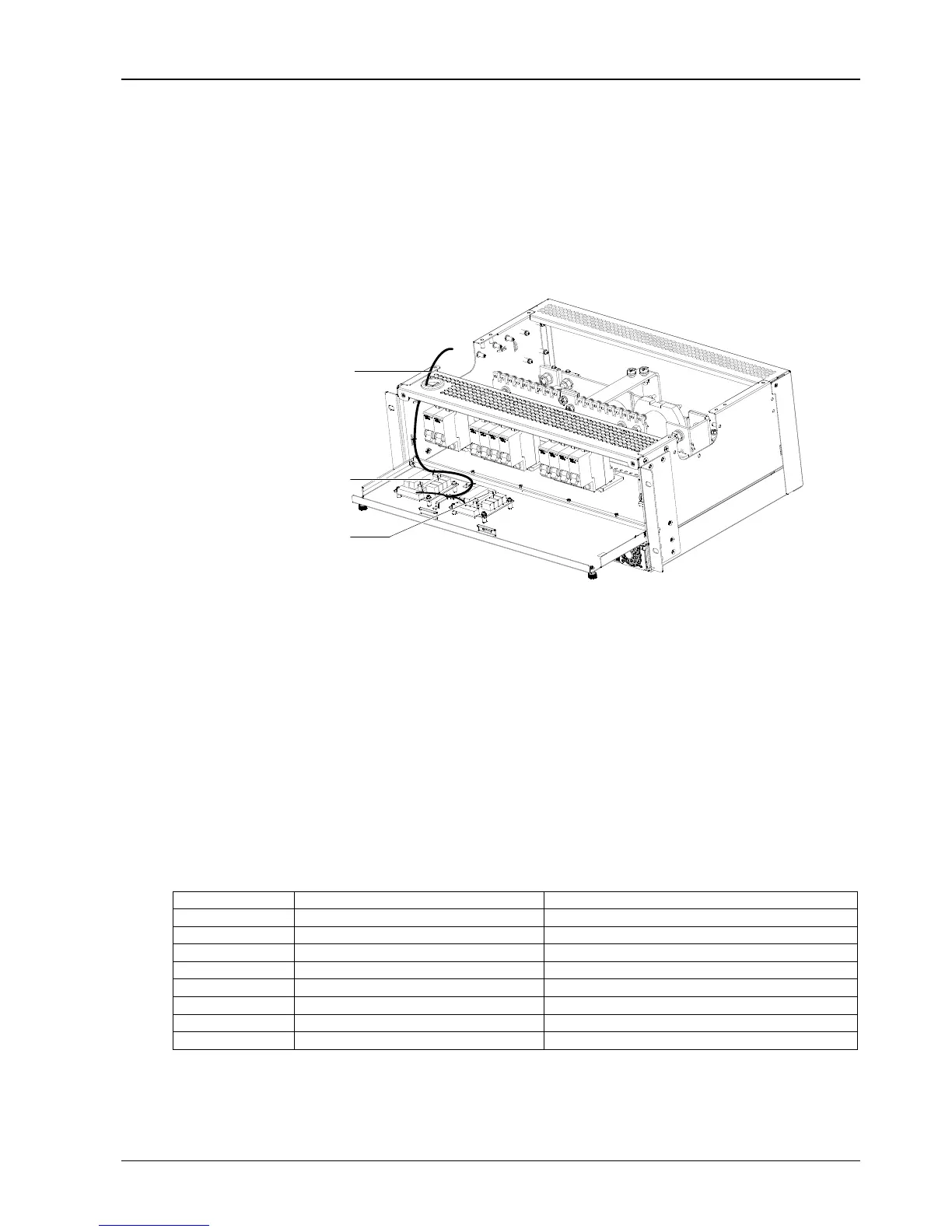
Take the NetSure 531 A41-S1 power system as an example, the position of the user connector board (W2453X1) is
shown in Figure 2-13.
Signal cable
User interface board
User interface board
(Flexible configuration)
Figure 2-13 W2453X1 user interface board Illustration
At most two user connector boards are allowed in the power system. Standard cabinet is only configured with one
user connector board.
With one user connector board configured, the power system provides three external digital signal input interfaces:
DI2, DI3, DI4 (DI1 is used for DC SPD alarm. If no DC SPD is configured in the power system, DI1 is available) and
four dry contact alarm output interfaces: DO1, DO2, DO3, DO4. With two user connector boards configured, the
power system provides additional four dry contact alarm output interfaces: DO5, DO6, DO7, and DO8.
Active dry contact need to be connected to the digital input port of the W2453X1 user interface board. The
specifications of the dry contact interface are as follows:
Digital inputs: opto-isolation, the alarm and power frequency is definable (high power level: 20V ~ 60V, low power
level: less than 1V).
Digital output: relay isolation, Max.:30Vdc/1A, 125Vac/0.5A, 60W; Min.: 10uA@10Vdc, alarm is definable.
The functions of the interfaces are shown in Table 2-5.
Table 2-5 Nterface functions
DC overvoltage or DC undervoltage
Four-level DC voltage alarms
Except rectifier lost and multi-rectifier alarm
Exist when the second user interface board is installed
Exist when the second user interface board is installed
Exist when the second user interface board is installed
Exist when the second user interface board is installed
With default settings, when the preceding alarms are generated, the contactors of the corresponding dry contacts
should change their status, that is, the normally-open contactors close, and the normally-closed contactors open. All
the status changes should be verified by a multimeter. After the alarms are removed, the dry contacts should resume.

 Loading...


