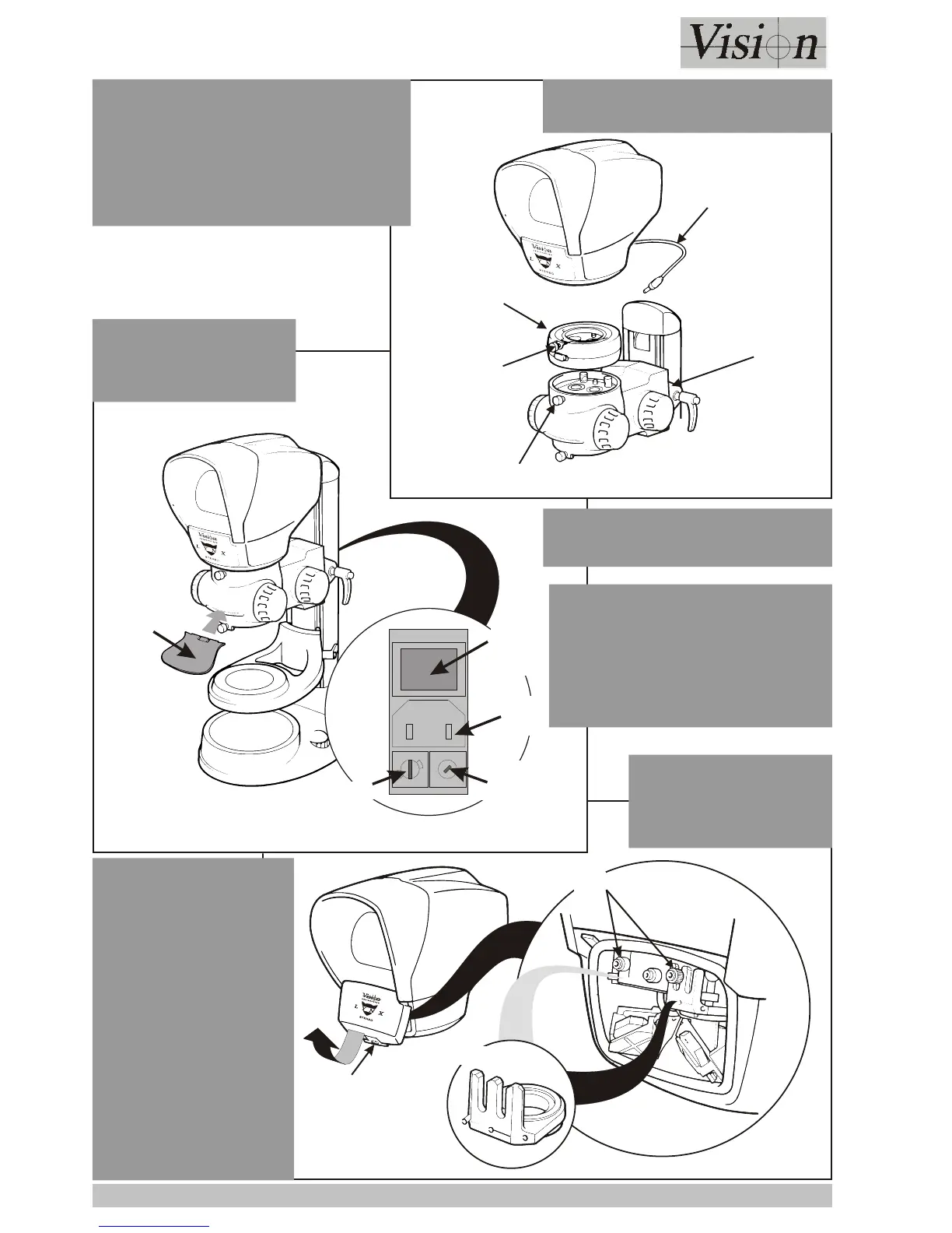
EasyManuals Logo
Home>Vision>Microscope>Lynx Stereo

Vision Lynx Stereo User Manual

Vision Lynx Stereo
21 pages
To Next Page IconTo Next Page
To Previous Page IconTo Previous Page
Page #14 background imageLoading...
Page #14 background image
Page 8
ASSEMBLY
Securing Clip
Retaining Knobs
Graticule
Connect Mains
at Rear
1
15
2
3
0
Mains
On/Off
Switch
Anti-glare
Shield
Mains
Input
Voltage
Selector
Fuse
MAINS
CONNECTION
Head
Connector
Zoom
Multiplier
Head
Socket
Securing Screw
Head
Securing Screw
ZOOM MULTIPLIER
Remove the Head. Place the Zoom
Multiplier Assembly into position and
tighten the securing screw.
Replace the Head on to the assembly
and tighten the Head Securing
NOTE
Ensure the Voltage Selector is
turned to the correct setting.
For Japan and some Far
Eastern markets the voltage
selector is marked 100 - 110V.
INSERTING
GRATICULE
Squeeze the securing
clip at the base of the
front cover and lift the
cover off. Loosen the
appropriate retaining
knob (the graticule
can be placed on
either side of the
head), slide the
graticule into position
and re-tighten the
knob. Replace the
front cover.
Attach the anti-glare shield as
shown left.

Questions and Answers:

Question and Answer IconNeed help?

Do you have a question about the Vision Lynx Stereo and is the answer not in the manual?

Vision Lynx Stereo Specifications

General IconGeneral
BrandVision
ModelLynx Stereo
CategoryMicroscope
LanguageEnglish