appears on the display, this indicates that there is no communication link between the unit and control panel. In this instance no local adjustment is
allowed.
Note: If no buttons are pressed within 20 seconds, the digital display turns off.
2. Change the threshold by pressing the "Up" or "Down" button.
Note: The lower the threshold, the higher the sensitivity, therefore, the lowest thresholds are more suitable for harder materials, such as
concrete.
3. While the SD-304C PG2 threshold menu is active, knock on the surface with the required force for the detector to set the required threshold. The
power of the detected knock is presented on the display of the SD-304C PG2 as a blinking number for 3 seconds. The displayed number will be in
the range of 1 to 19, where 1 is very weak and 19 is very strong.
Note: Note: If the installer knocks on the surface but nothing appears on the display, this indicates that no shock is detected. If a hyphen blinks, this
indicates that the knock is above the highest threshold of the detector.
4. Repeat the same test several times.
5. Press the "Up" or "Down" button to navigate to the threshold number to be set and then press the "Up" and "Down" buttons simultaneously to set
the threshold.
6. The detector now moves to the next menu, the Accumulated menu (shown as "A" on the display). Press the "Up" or "Down" buttons to Enable ("1"
on the display) or Disable ("0" on the display) the Accumulation mode. Press the "Up" or "Down" buttons simultaneously to set the selected option.
Note: When Accumulation is enabled, the power of impact will still indicate the strength of a single knock, therefore, it is recommended to disable
this parameter while the Threshold is tested and to enable the Accumulation mode only after setting the Threshold.
7. If after the "Up" and "Down" buttons are simultaneously pressed the letter “E” appears, this likely indicates that there is no communication link
between the unit and control panel. Check if the panel is properly powered.
Note: The parameters that are set locally are saved on the control panel and are automatically downloaded to the detector either on power up or
tamper closure.
3. LOCAL DIAGNOSTICS TEST
Before testing, separate the base from the cover (see Figure 3).
A. Press the tamper switch once and release it.
B. Put back the cover to return the tamper switch to its normal (undisturbed) position, and then secure the front cover to the base with the case
closure screw.
C. Use a hammer to apply shock in close proximity to the detector and verify the red LED blinks, indicating detection.
D. After 2 seconds the LED blinks 3 times.
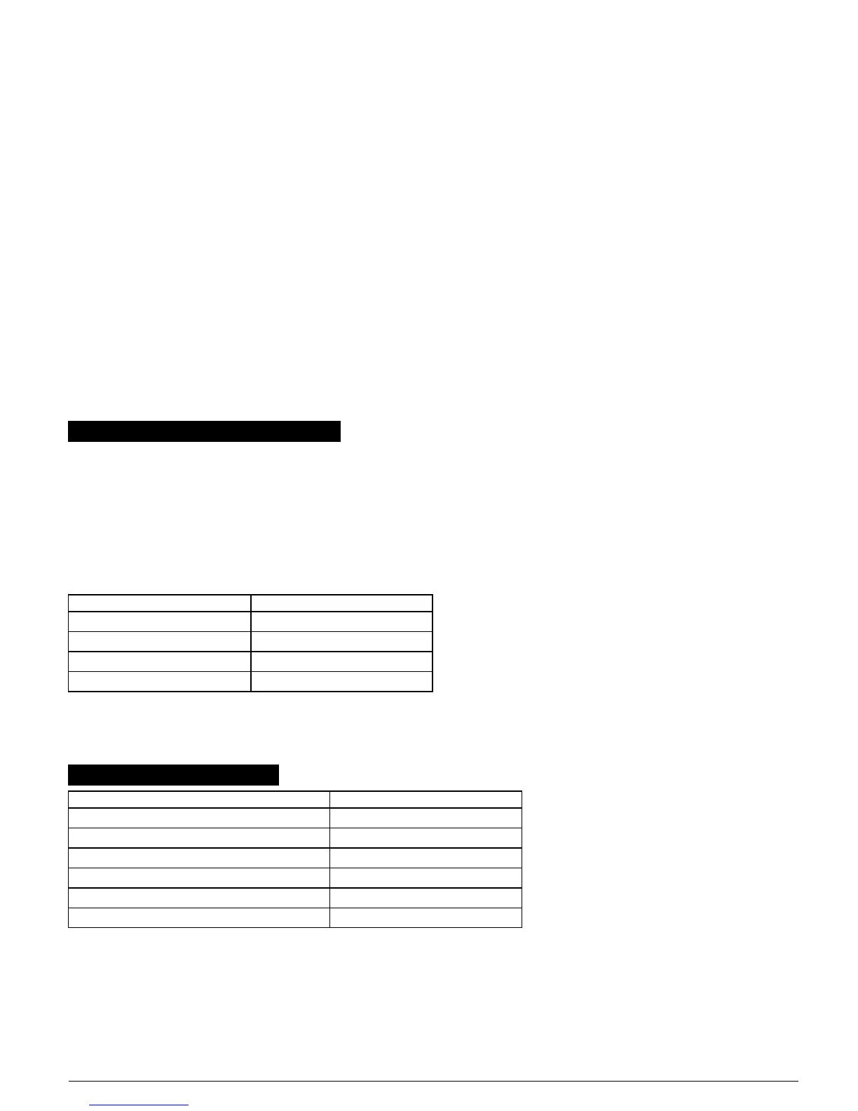
The following table indicates received signal strength indication.
LED response Reception
Green LED blinks Strong
Orange LED blinks Good
Red LED blinks Poor
No blinks No communication
Important! Reliable reception must be assured. Therefore, "poor" signal strength is not acceptable. If you receive a "poor" signal from the detector, re-
locate it and re-test until a "good" or "strong" signal strength is received.
Note: For detailed Diagnostics Test instructions refer to the control panel Installer Guide.
4. EVENT INDICATIONS
LED Indications Event
Red LED ON 0.2 sec. Tamper open / close
Red on 2 sec. Shock
Red on 2 sec. Open close door
Red on 2 sec. Open close Aux input
Yellow LED on AM detection in local diagnostic mode
Yellow LED blinks slowly (0.2 sec. ON, 30 sec. OFF) AM detection in normal mode
D-304286 SD-304C PG2 Installation Instructions 4
 Loading...