70
Maintenance. Electrical component diagrams
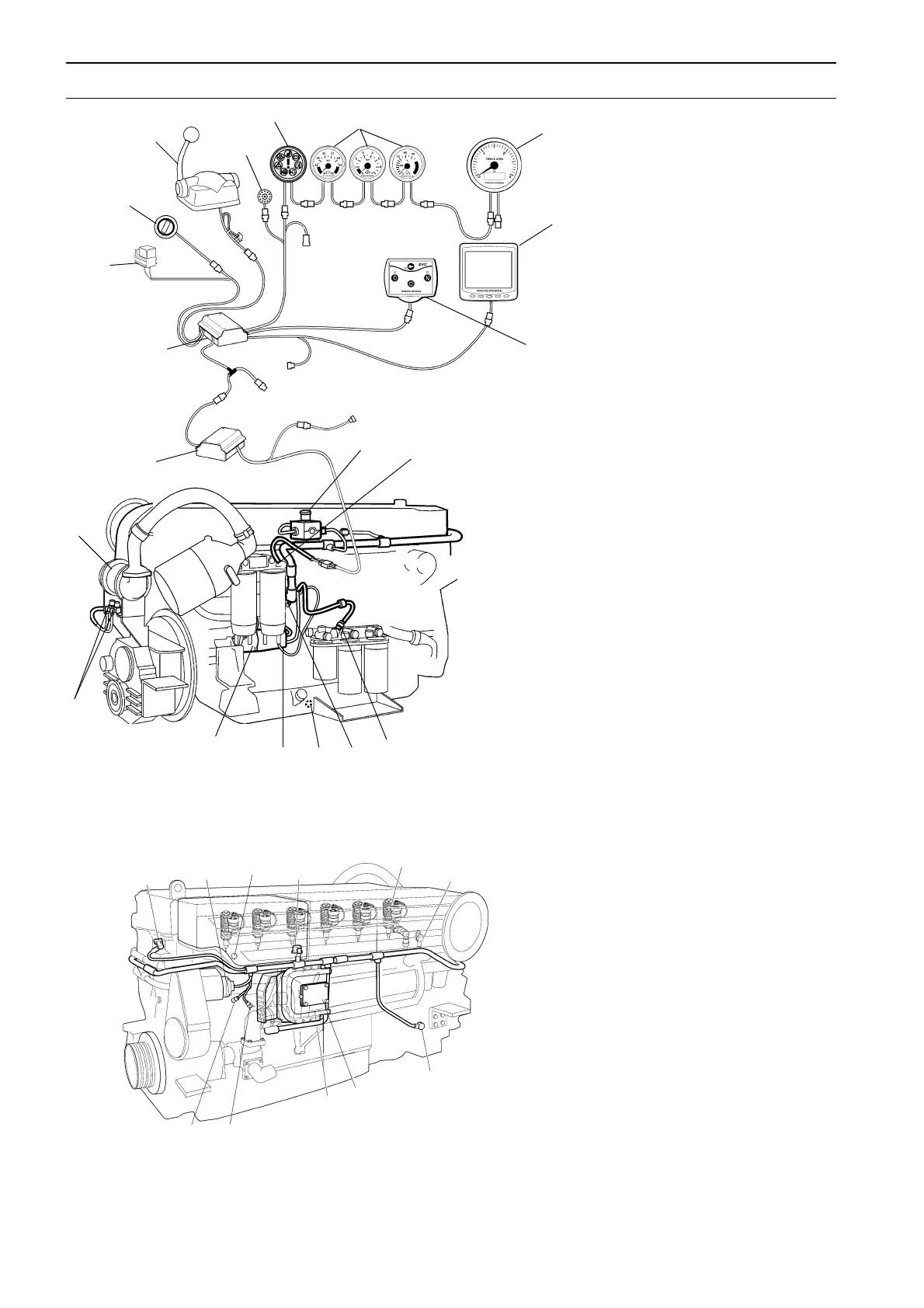
Electrical component diagrams
D12D-A MP
1. Power train control unit (PCU)
2. Helm station control unit (HCU)
3. Relay for external accessories
4. Key switch
5. Control lever
6. Buzzer
7. Alarm display
8. Instruments
- Voltmeter
- Oil pressure gauge
- Temperature gauge
9. Tachometer
10. EVC display
11. EVC control panel
12. Emergency stop
13. Sensor, fuel pressure
14. Sensor, oil pressure piston cooling
15. Connector (synchronisation)
16. Switch, oil level alarm (optional)
17. Switch, water in fuel
18. Starter motor (with starter motor
solenoid)
19. Shift solenoids, reverse gear
20. Sensor, oil pressure reverse gear
21. Sensor, camshaft position
22. Alternator
23. Switch, coolant level alarm (optional)
24. Combined sensor, charge pressure/
charge temperature
25. Unit injector
26. Sensor, coolant temperature
27. Sensor, flywheel position and engine
speed
28. Power modul
29. Control unit (with atmospheric pres-
sure sensor)
30. Combined sensor, oil pressure/oil
temperature
31. Sensor, crankcase pressure
1
2
3
4
5
6
87
9
10
11
12
13
14
15
16
17
18
19
20
21 26
25
24
23
22
31 30
29
28
27
 Loading...