Portable Generator Repair G 3.7A;G/GS 5.6A;GS 8.5V;GS 9.7V
wc_tx000208gb.fm 61
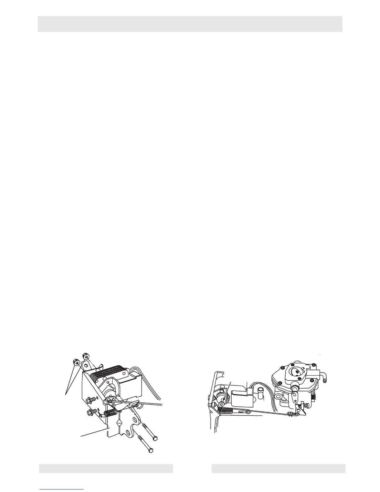
6.17 Removing and Installing Electronic Governor (GS 8.5V and
GS 9.7V Models)
See Graphic: wc_gr000945
Removing
6.17.1 Disconnect RED and GREEN wires from control module to actuator.
6.17.2 Remove air cleaner assembly.
6.17.3 Disconnect governor link at carburetor.
6.17.4 Remove governor control bracket with actuator.
6.17.5 Disconnect governor link from actuator and remove throttle return
spring.
6.17.6 Remove screws, nuts and actuator from control bracket.
Installing
6.17.1 Assemble actuator to governor control bracket (a).
Torque screws and nuts to 3.4 Nm (30 in. lbs.) (b).
Note:
Hold the long screws with a ¼-inch wrench when torquing nuts.
Screws must NOT turn while torquing nuts.
6.17.2 Assemble governor link to actuator. Make sure link snaps into hole in
actuator grommet.
6.17.3 Assemble throttle return spring through slot in governor control bracket
with open end spring facing out and through small hole in governor
bracket.
6.17.4 Assemble governor control bracket assembly to engine.
• Torque four 8mm screws to 17.0 Nm (150 in. lbs.).
• Torque two 6mm screws to 10.0 Nm (70 in. lbs.).
6.17.5 Rotate the actuator lever to position shown (c) and connect governor
link to carburetor.
6.17.6 Connect RED and GREEN wires from the control module to actuator.
a
b
wc_tx000945
c
 Loading...