Page 31
3.3 Unpacking
The unit is supplied on a small pallet and is covered with a cardboard box. The cardboard box
should be removed to reveal the unit with the supplied components located in the recessed
back panel. The unit is attached to the pallet using screws. These must be removed before
trying to remove the unit from the pallet. The unit can then be slid off the pallet and located into
position. Care should be taken to ensure that the unit does not tilt more than 45° when being
moved around as this can cause internal damage.
3.4 Heating Circuit Connection
3.4.1 Heating Medium
The heating system should be completely flushed to remove impurities and deposits from
sealants and fluxes. The heating circuit should be flushed, purged and pressure tested
according to MCS guide MIS3005 and to the relevant Building Regulations. An inhibitor should
be added to the water to prevent corrosion, scale and bacteria growth. This should be added
according to the inhibitor manufacturer’s guidelines. Glycol should be added to the system in
areas where the ambient temperature drops below freezing. The amount of Glycol to be added
should be determined according to the manufacturer’s instruction. Warmflow provide a non-
toxic glycol solution complete with corrosion, scale and biological inhibitor.
3.4.2 Heating Connections to the Heat Pump
The unit comes with female union fittings for the heating flow and return connections. Two
flexible hoses with connections to attach to the female unions are included with the unit. These
should be used to reduce any vibration or noise which may be transferred to rigid pipe or the
building structure.
3.4.3 Heating Circuit and Integrated Circulator
A variable speed high efficiency circulator for the heating circuit is provided within the casing of
each unit. The circulators have been sized to accommodate the majority of heating systems
based on the heat output of each unit. However, due to the variation in each system, checking
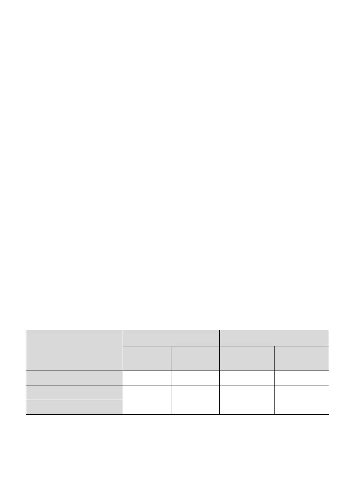
that the minimum required flow rate is achievable is essential. The table below shows the
minimum and maximum required flow rates for each unit at minimum and maximum heat
outputs respectfully.
Table 6 Heating flow rate requirements
Required Flow Rate (l/min)
3.4.4 Bypass / Open Zones
It is essential that the heating circuit can always achieve a minimum flow rate of at least 10 litres
per minute even when no zones are calling for heat. This can be achieved by fitting a bypass
between the flow and return or by leaving a number of zones/radiators permanently on. This
 Loading...