Page 35
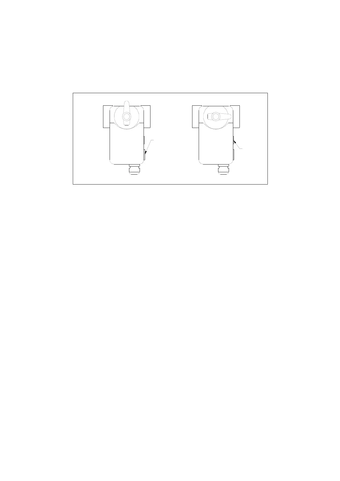
The valve turns clockwise when DHW is enabled as shown on the right in Figure 28 above with
flow from A to B. With the valve body in the default position, the actuator should then be set to
the default position as shown on the left in Figure 29 below. This can be achieved by holding
down the clutch release button (located on the right side of the actuator) and rotating the lever
into the correct position. The actuator should then be clipped onto the valve body. A rotation
switch can be found on the right side of the actuator and must be in the ‘CW’ (clockwise)
position.
A B A B
Rotation
Switch set to
'CW'
Clutch
Release
Button
Figure 29 3-port Motorised Valve Actuator Positions
The valve turns clockwise when DHW is enabled as shown on the right in the figure above.
The valve actuator is 230V ac and has 3 wires, a brown, a blue and a white wire. The brown
wire is the permanent live to the valve to power it in order to return to the default position and
should be wired into the permanent live connection in the installers wiring enclosure. The white
wire is the switched power which powers the valve to the DHW position when DHW mode is
active. This should be wired into terminal 22 in the installers wiring enclosure. The blue wire is
the neutral and should be wired into terminal 23 in the installers wiring enclosure.
3.10 Electrical Installation
Together with the connection to the mains, there are a number of sensors and input/output
connections which must be made with the heat pump. These connections are to be made in the
installers wiring enclosure. The installers wiring enclosure can be found under the removable
plastic cover panel of the heat pump casing.
The installer’s wiring enclosure contains the entire necessary connection terminals for
installation.
Electrical installation including cable sizing and protection should only be undertaken by a
qualified electrician in accordance with the latest Institute of Electrical Engineers (IEE)
regulations.
3.10.1 Incoming Supply
The AS01, AS02 & AS03 units all require a single phase 230V
ac
50Hz electricity supply. The
AS01 is rated at 9Amps whilst the AS02 is rated at 18Amps* and the AS03 is rated at 27Amps.
As these units are variable speed, during starting the compressor speed is ramped up slowly
meaning there is not a high starting current commonly associated with fixed speed units and as
such there is no need for a very large power supply or the use of starting capacitors.
The units must be protected by a Type C MCB and RCD according to the table below.
 Loading...