Page 34
3.5 Defrosting
Due to the nature of the heat pump operating cycle, frost and ice may build-up on the
evaporator. The unit senses this build-up and then performs a defrost cycle to get rid of this ice.
As a result, the ice is melted and collects in the drip tray. The trip tray is heated to prevent this
water from refreezing. Holes in the bottom of the drip tray allow the water to exit the heat pump.
Adequate provision should be made to prevent condensate from collecting around the units. A
soak away underneath the unit or drip tray should be used as deemed appropriate to the site.
3.6 Air Vent
Each unit features a manual air vent located at the top of the unit (internal on some models,
external on others). This is to allow air to be removed from the unit when it is filling.
NOTE: For models with an internal manual air vent, a piece of piping must be fitted to
the air vent before opening it to ensure no water is sprayed onto any electrical
components in the casing.
3.7 Buffer tank
In order to perform the defrost cycle, the unit runs in reverse mode. This operation takes a
small amount of heat from the heating system and uses it to melt the ice which has formed on
the evaporator. In order to do this effectively, it is recommended to have an in line buffer tank
on the return heating pipework to the unit. An open circuit must always be maintained to allow
defrosting to occur. A buffer is available separately from Warmflow.
3.8 Bypass Valve
In order to provide sufficient flow rates and to facilitate defrosting, it is essential that the heating
circuit can always achieve a minimum flow rate of at least 10 litres per minute even when no
zones are calling for heat. This can be achieved by fitting a bypass between the flow and return
or by leaving a number of zones/radiators permanently on. This will significantly reduce short
cycling and nuisance alarms such as low flow rate. It is also essential to provide freeze
protection as detailed in section 3.4.5. An open circuit must always be maintained to allow
defrosting to occur.
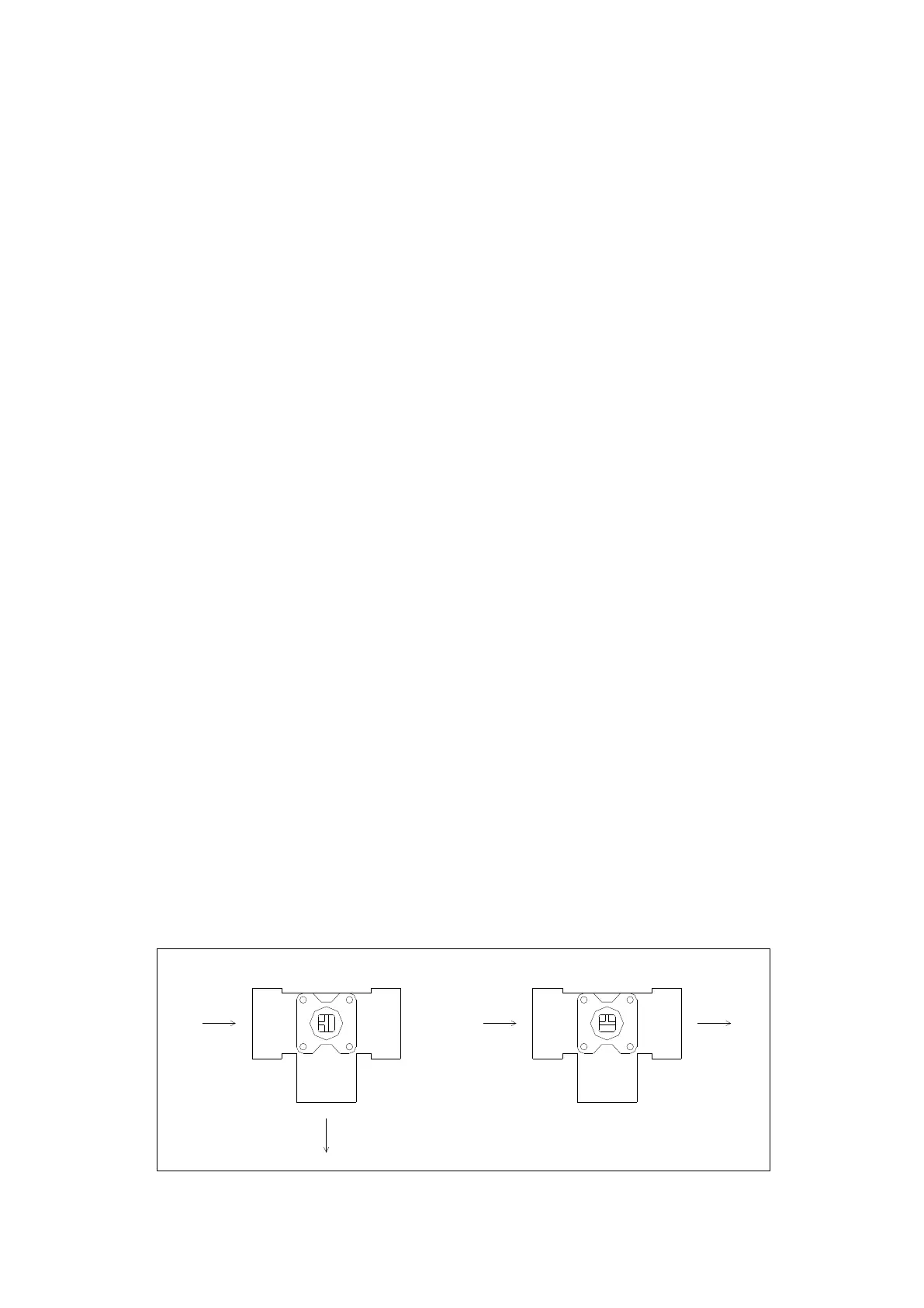
3.9 3-Port Motorised Valve
A full flow 3-port motorised valve is available separately. This 3-port motorised valve has a
number of operating positions and comes in two parts, the valve body and the actuator. It is
essential that the valve body position and actuator are positioned correctly to ensure
appropriate functionality. The valve body position is adjusted by a ‘T’ on top of the valve. The
default position of the ‘T’ is shown on the left in Figure 28 below. The default position is for
heating with flow from A to AB.
A B
AB
A B
AB
Flow from
Heat Pump
Flow from
Heat Pump
Flow to
DHW
Flow to
Heating
Figure 28 3-port Motorised Valve Body Positions
 Loading...