DVS/GSE GSE DVS Field Service Manual
09030-78B 39 of 49
Webasto Charging Systems, Inc.
If problem still persists, clip leads from a multimeter across 120VAC input terminals and set
multimeter to read AC voltages. Turn power on at utility disconnect and observe voltage readout.
If no voltage is present, troubleshoot 120VAC circuitry per section 3.4.7. If 120VAC circuitry is
working properly, troubleshoot contactor enable relay K3 per section 3.4.11, thermal sense
system per sections 3.4.8 and 3.4.11, and pre-charge sense system per section 3.4.10.
If 120VAC is present at the contactor input and the green indicator light comes on within one
minute of turning on power, but contactor does not close, turn of power at utility disconnect,
replace contactor, and re-test.
3.4.6 Diagnosing Root Cause for Red Fault Light Illumination
Turn off power to the DVS at the utility disconnect. Lock and tag disconnect. Check all thermal
switches and troubleshoot potential thermal issues per section 3.4.8. If problem persists, check
utility voltage per section 3.4.3. If problem persists, troubleshoot transformer T2 per section
3.4.8.
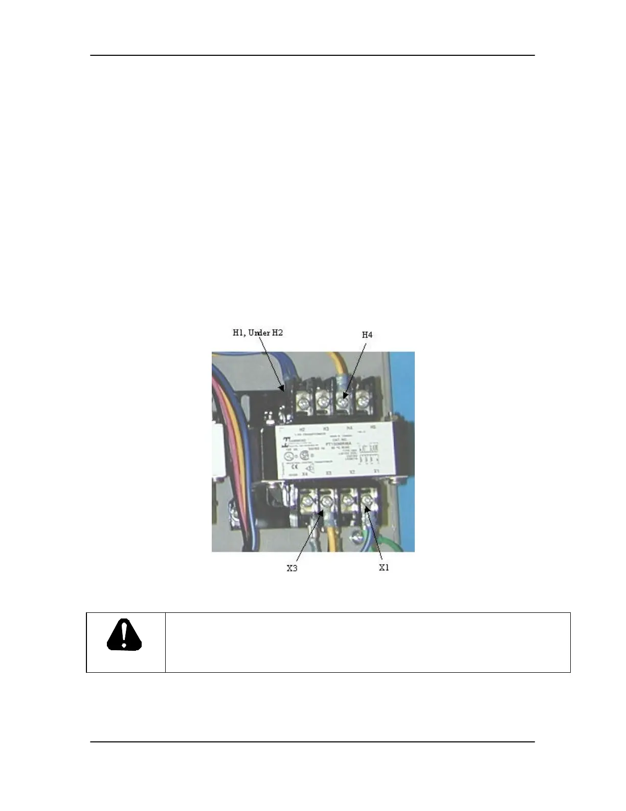
3.4.7 Troubleshooting Main 120VAC Circuit
Figure 8. Main 120VAC Transformer, T3
DANGER
USE EXTREME CAUTION WHEN TROUBLESHOOTING THE DVS
WITH ANY PANEL REMOVED. ELECTRIC SHOCK CAN KILL:
Touching live electrical parts can cause fatal shocks or severe burns. The input
power circuitry and internal circuits are live whenever input power is on.
Check continuity of fuses F1 and F3. If either fuse is blown, check internal wiring throughout
Power Supply Cabinet, correct any wiring problems, and replace blown fuse. If problem persists,
turn utility power on. Using extreme caution, check voltages per the following table:

 Loading...