DVS/GSE GSE DVS Field Service Manual
09030-78B 43 of 49
Webasto Charging Systems, Inc.
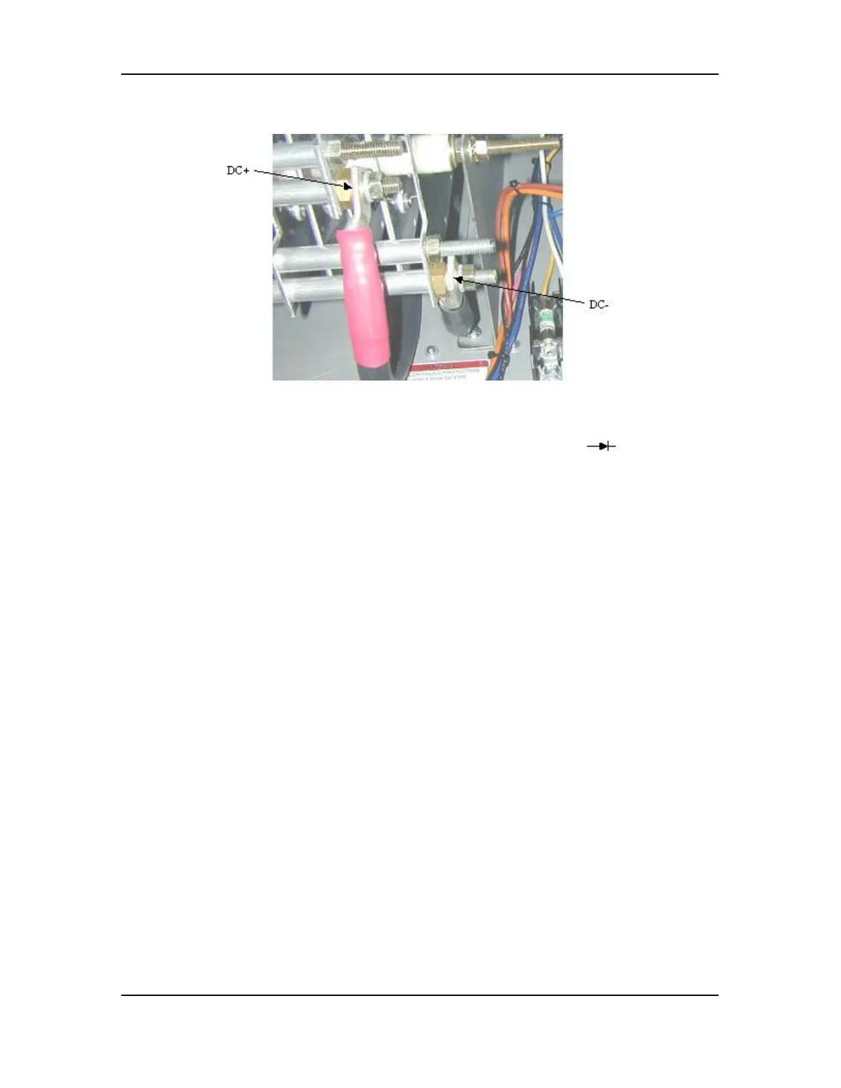
Figure 12. D1 DC Connections
The Diode Test Mode of your Fluke DMM will be indicated by the symbol . Using the
Diode Test mode, measure voltage across the following points on each rectifier:
DC+ to Each AC Input
DC- to Each AC Input
If any voltage measurement is less than 0.1VDC, replace rectifier and re-test.
3.4.10 Troubleshooting Pre -Charge Circuitry
Troubleshoot relays K2, and K3 per section 3.4.11. Check output of transformer T3 per section
3.4.8. Troubleshoot thermal system per section 3.4.8. Check fuses F1, F2 and F3 per section
3.4.4.
3.4.11 Testing Relays K2 and K3
Turn off power to the DVS at the utility disconnect. Lock and tag disconnect. Remove front
panel of Power Supply Cabinet. First test per Table 5, “System Off” values with system power
off. Next, turn system power on at utility disconnect and re-test per, “System On” values. Unless
otherwise noted, “System On” values refer to values present when the system is on and fully
functional with the 150VDC bus enabled and the green indicator light on.

 Loading...