Specialized Concentrated Focused
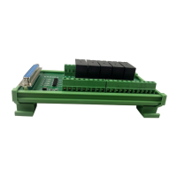
Wiring「19」
encoder after
cycle divided)
Numerator of
Electronic Gear
Ratio
Pn202 = pulse number of each encoder circle × 4 ×
mechanical deceleration ratio
Pn203 = (screw pitch / pulse equivalent)
Typical value: pitch 5mm, encoder 17-bit,
deceleration ratio 1:1, pulse equivalent 0.001mm,
Pn202=16384; Pn203=625.
pitch 5mm, encoder 17-bit, deceleration ratio 1:1,
pulse equivalent 0.0005mm, Pn202=8192; Pn203
=625
Denominator of
Electronic Gear
Ratio
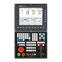
3.6.3 Parameter Setting of DELTA ASDA_ A Servo Driver
Monitor if the number of sent and received pulse
is correct by setting this parameter. In Weihong
control system, the correct quantity of pulse sent
by control card is detected by pulse inspection to
determine if there is electrical interference.
External pulse
input type
X=2: pulse + direction;
Z=1: negative logic
Z=0: when switching control mode, DIO is
maintaining the set value. Since switching
control mode is not used, Z=0
Y=0: forward rotation (anticlockwise) (from the
point of load);
Y=1: the rotation direction is reversed.
X1X0=00: position control mode
Numerator of
Electronic
Gear Ratio,
(N1)
N1 / M= encoder pulses× 4× pulse equivalent×
mechanical deceleration ratio / pitch.
Representative value: encoder pulses 2500,
pulse equivalent 0.001, pitch 5mm, mechanical
deceleration ratio 1, calculation as below:
N1 / M= 2500×4×0.001/5 = 2 / 1, N1=2, M=1;
When the multi-electronic gear ratio is not used,
P2-60~ P2-62 are not required.
Denominator
of Electronic
Gear Ratio,
(M)
0: Servo ON must be triggered by numerical
input signal.
 Loading...