Installation and operating instruction
Gas burner WG20…/1-C Z-LN
3 Product description
83054602 1/2020-01 La
12-96
3.3.2 Gas supply
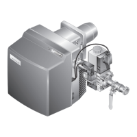
Gas isolating valve 1
The gas isolating valve opens and shuts off the gas supply.
Multifunction assembly8
The multifunction assembly contains:
Gas filter 2 The gas filter protects the subsequent valve train
components from foreign particles.
Double gas valve 4 The double gas valve opens and shuts off the gas
supply.
Pressure regulator 3 The pressure regulator reduces the connection
pressure and ensures a constant setting pressure.
Gas butterfly valve 5
The gas butterfly valve regulates the gas quantity depending on the rating required.
The air/gas ratio is adapted via mechanical compound to the air damper setting.
Low gas pressure switch/ valve proving gas pressure switch 7
The gas pressure switch monitors the gas connection pressure. If the preset pres-
sure is not achieved, the combustion manager initiates a safety shutdown.
The gas pressure switch also monitors if the gas valves are tight. It signals the
combustion manager if the pressure increases or decreases to an impermissible
level during valve proving.
Valve proving is carried out automatically by the combustion manager:
after every controlled shutdown,
prior to burner start following lockout or power outage.
1. Test phase (function sequence for valve proving valve1):
Valve 1 closes,
valve 2 closes after a delay,
the gas escapes and the pressure between valve 1 and valve 2 reduces,
both valves remain closed for 8 seconds.
If the pressure increases to above the value set during these 8 seconds, valve1 is
leaking. The combustion manager initiates a controlled shutdown.
2. Test phase (function sequence for valve proving valve2):
Valve 1 opens, valve 2 remains closed,
pressure between valve1 and valve2 increases,
valve 1 closes again,
both valves remain closed for 16 seconds.
If the pressure decreases to below the value set during these 16 seconds, valve2
is leaking. The combustion manager initiates a controlled shutdown.
 Loading...
