975-0136-01-01 vii
Figure 1 Example of Multi-Drop Backbone - - - - - - - - - - - - - - - - - - - - - - - - - - - - - - - - - - - - - - -3
Figure 2 Multi-Drop Backbone Layout - - - - - - - - - - - - - - - - - - - - - - - - - - - - - - - - - - - - - - - - - -5
Figure 3 Daisy Chain Layout- - - - - - - - - - - - - - - - - - - - - - - - - - - - - - - - - - - - - - - - - - - - - - - - -6
Figure 4 3-Way Network Connector (sample configuration)- - - - - - - - - - - - - - - - - - - - - - - - - - - -7
Figure 5 Network Terminators- - - - - - - - - - - - - - - - - - - - - - - - - - - - - - - - - - - - - - - - - - - - - - - -8
Figure 6 RJ45 Connector - - - - - - - - - - - - - - - - - - - - - - - - - - - - - - - - - - - - - - - - - - - - - - - - - - -9
Figure 7 Recommended Mounting Orientation for Network Connector - - - - - - - - - - - - - - - - - - -13
Figure 8 Options for Completing a Multi-Drop Backbone Layout - - - - - - - - - - - - - - - - - - - - - - - 14
Figure 9 Completing a Daisy-Chain Layout - - - - - - - - - - - - - - - - - - - - - - - - - - - - - - - - - - - - - -15
Figure 10 Select Device Menu- - - - - - - - - - - - - - - - - - - - - - - - - - - - - - - - - - - - - - - - - - - - - - - - 16
Figure 11 System Settings Menu - - - - - - - - - - - - - - - - - - - - - - - - - - - - - - - - - - - - - - - - - - - - - - 16
Figure 12 Safe Mode - - - - - - - - - - - - - - - - - - - - - - - - - - - - - - - - - - - - - - - - - - - - - - - - - - - - - - 17
Figure 13 System Home Screen- - - - - - - - - - - - - - - - - - - - - - - - - - - - - - - - - - - - - - - - - - - - - - - 18
Figure 14 System Settings: View Device Info - - - - - - - - - - - - - - - - - - - - - - - - - - - - - - - - - - - - - 19
Figure 15 Device Information Screen (RS2000 used for example)- - - - - - - - - - - - - - - - - - - - - - - - 19
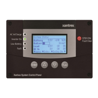
Figure 16 System Control Panel - - - - - - - - - - - - - - - - - - - - - - - - - - - - - - - - - - - - - - - - - - - - - - 20
Figure 17 Operate Mode- - - - - - - - - - - - - - - - - - - - - - - - - - - - - - - - - - - - - - - - - - - - - - - - - - - - 21
Figure 18 Entering Power Save Mode- - - - - - - - - - - - - - - - - - - - - - - - - - - - - - - - - - - - - - - - - - - 22
Figure 19 Hibernate Mode - - - - - - - - - - - - - - - - - - - - - - - - - - - - - - - - - - - - - - - - - - - - - - - - - - 22
:
CAUTION: Equipment damage
Connect the Xanbus System only to Xanbus compatible devices.
Although the cabling and connectors used in this network system are the same as
Ethernet connectors, this network is not an Ethernet system. Equipment
damage may result from attempting to connect these two different systems.
Figures
