Repairs and Adjustments
Phaser® 3500 Laser Printer Service Manual
4-47
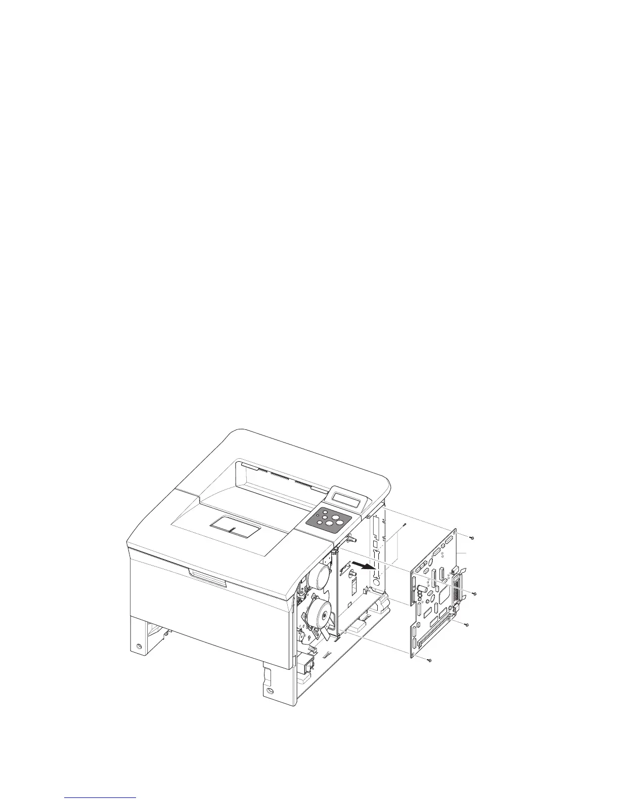
Main Board and Shield
Note: If the NIC Board is installed, it must be removed to access screws to the main
board.
NVRAM parameters are not transferable to the replacement board. These parameters
include serial number and copy count. Serial Number can be reinstalled via CentreWare IS
if the NIC Board is installed or via a downloadable PJL command. Observe proper ESD
procedures when removing or replacing any circuit boards in the printer.
1. Remove:
■ Covers on page 4-4
2. Disconnect all connectors from the Main Board.
3. Remove the NIC card or the dummy bracket from the main board.
4. Remove the 6 screws (4 on the Main Board and 2 to the parallel connector) securing the
Main Board to the printer, and then remove the Main Board.
5. Position the retainers on the parallel port connector straight out from the connector for
removal.
6. Move the board toward the front of the printer so the connectors clear the bracket and
remove the Main Board to the right.
7. Remove 1 screw in the center of the shield.
8. Turn the printer onto its left side and remove the rear crossbar and the right duplex guide.
9. Remove the right rear corner screw from the power supply shield to remove.
Main PB
s3500-071
 Loading...