12 www.xilinx.com Spartan-6 FPGA GTP Transceiver SIS Kit (HyperLynx)
UG396 (v1.0) June 10, 2010
Chapter 1: Spartan-6 FPGA GTP Transceiver Signal Integrity Simulation Kit
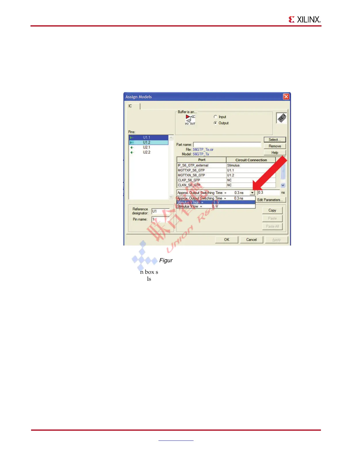
The setting for the Approx. Output Switching Time = 0.3 ns drop-down box shown
in Figure 1-4 is meant to be the SPICE driver output (not stimulus) rise or fall time and
is used to set the step size and estimate crosstalk effects in the simulation. The value of
this parameter can be changed if desired. Relaxing this parameter allows the user to
select larger simulation time steps in the Run Eldo/ADMS Simulation dialog box,
which might result in non-converging simulations.
The drop-down box shown in Figure 1-4 has two additional entries for the High and
Low voltage levels of the stimulus generated by HyperLynx. Do not modify these
numbers because they are closely related to the content of the netlist. The voltage
levels in the GTP_RefClk.ffs testbench must be set to –1V for Stimulus V low
and +1V for Stimulus V high. In the rest of the testbenches, they should be set to 0V
for Stimulus V low and +1V for Stimulus V high.
3. When the desired changes are made, click on the OK button to close the Assign
Models dialog box.
Customizing the Channel Representation
Use the available HyperLynx toolbox to add S-parameter models, transmission lines, vias,
and so forth.
The provided example contains an S-parameter model representing a 20-inch microstrip
trace with SMA connectors on each side. The board material is FR-4. A custom channel
representation can be created using the HyperLynx toolbox to add S-parameter models,
transmission lines, vias, and so forth.
X-Ref Target - Figure 1-4
Figure 1-4: Output Switching Time

 Loading...