16 www.xilinx.com Spartan-6 FPGA GTP Transceiver SIS Kit (HyperLynx)
UG396 (v1.0) June 10, 2010
Chapter 1: Spartan-6 FPGA GTP Transceiver Signal Integrity Simulation Kit
• The radio buttons in the IC modeling group (Figure 1-6) are ineffective because the
simulation corner selections are made using the Configure Model button in the
Assign Models dialog box.
• Checkboxes with the red SPICE label on their left (Figure 1-6) represent schematic
symbol nodes that are connected to NC in the Assign Models dialog box. These
nodes are defined on the subcircuit definition line of the symbol. They do not need to
be connected to anything else on the schematics because they are used solely to
provide probing capabilities for waveforms inside the subcircuits.
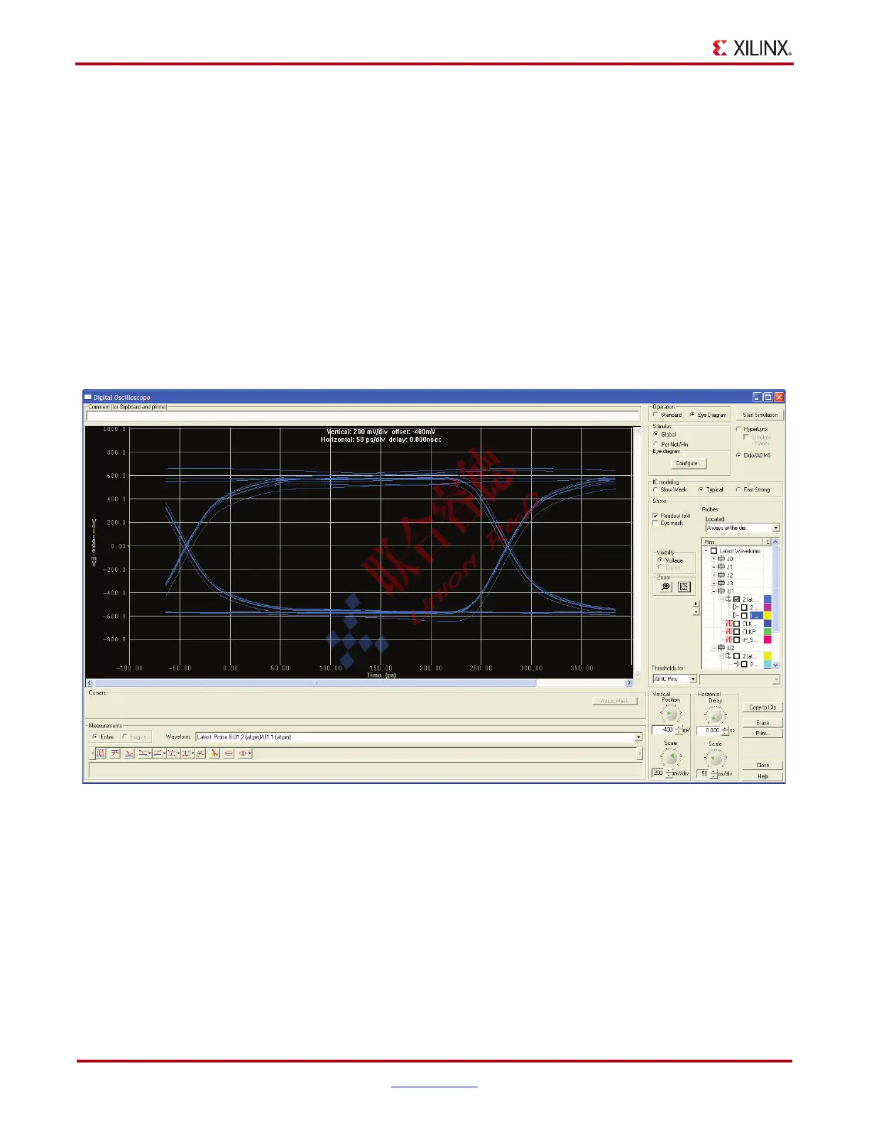
Running the Simulation
Click the Start Simulation button and wait for the simulator to finish the simulation. The
waveform window automatically displays the results for the selected waveforms in the
oscilloscope. The vertical and horizontal scales can be adjusted to maximize the
waveforms, as shown in Figure 1-8.
X-Ref Target - Figure 1-8
Figure 1-8: Example Simulation Results

 Loading...