EasyManua.ls Logo

Xinje VB5 User Manual

Xinje VB5
110 pages
To Next Page IconTo Next Page
To Previous Page IconTo Previous Page
Page #85 background image
V5 series inverter
77
P7.06 Min setting value Range: 0.0~Max setting value 0.0%
P7.07 Feedback value corresponding to min setting Range: 0.0~100.0 (%) 0.0%
P7.08 Max setting value Range: min reference~100.0 (%) 100.0%
P7.09 Feedback value corresponding to max setting Range: 0.0%~100.0 (%) 100.0%
P7.06~P7.09 defines the relationship curve of analog close-loop setting value and expected feedback. See Fig4-36.
Fig. 4-36 setting and feedback curve
P7.10 Proportional gain KP Range: 0.000~9.999 0.050
P7.11 Integral gain KI Range: 0.000~9.999 0.050
P7.12 Sampling cycle T Range: 0.01~10.00s 1.00s
The bigger the proportion gain KP, the quicker the response, but too big may lead to surge easily.
Only adjust with proportiaon gian KP, deviation can not be eliminated, integral gain KI can be used to form PI control to
eliminate the deviation. The bigger the Ki, the quicker the response of changing deviation, but too big of the Ki may lead to
surge easily.
Sampling cycle T is the sampling cycle of feedback value. PI regulator calculates once in every sampling cycle, the longer
the cycle, the slower the response.
P7.13 Limit of deviation Range: 0.0~20.0(%) 2.0(%)
The max deviation value of close-loop setting is shown in Fig.4-37, if the feedback value is in this range, PI regulator will stop adjusting.
This function is useful to improve accuracy and stability of the system.
Fig.4-37 Limit of deviation Fig.4-38 close-loop preset frequency running
P7.14 Close loop adjustment characteristic Range: 0, 1 0
0: Positive. The motor speed increases with the increasing of setting value.
1: Negative. The motor speed decreases with the increasing of setting value.
Note: Define the relationship between setting value and speed.
P7.15 Integral adjustment selection Range: 0, 1 0
0: Stop integral adjustment when the frequency reaches upper limit or lower limit.
1: Continue the integral adjustment when the frequency reaches upper limit or lower limit.
For the system need quick response, it is better to cancel the continue integral adjustment.

Table of Contents

Question and Answer IconNeed help?

Do you have a question about the Xinje VB5 and is the answer not in the manual?

Xinje VB5 Specifications

General IconGeneral
ModelVB5
CategoryInverter
Output Power (DC Input)500W
Efficiency85%
Output Voltage (DC Input)220V AC
Protection FeaturesOverload, short circuit, over temperature, low voltage
Operating Temperature-10℃~50℃

Summary

Product Instruction

1-1. Product Overview

Provides a general introduction to the VB3/VB5/V5 series inverter's features.

1-2. Product Technical Specification

Details electrical and performance specifications for different inverter models.

1-3. Product Appearance

Describes the external design and layout of the inverter units.

1-4. Product Dimension

Provides physical dimensions and mounting details for various inverter models.

Installation and Wiring

2-1. Installation Environment

Specifies environmental conditions and mounting requirements for inverter installation.

2-2. Wiring

Covers general wiring precautions and procedures for power and control circuits.

2-3. Wiring of Main Circuit Terminals

Explains main circuit terminal assignments and their corresponding product types.

2-4. Basic Running Wiring

Illustrates a typical wiring diagram for basic inverter operation.

2-5. Setting and Wiring of Control Circuit

Details the control circuit terminals, jumpers, and their functions.

2-6. Mounting Guide According with EMC

Offers guidance on mounting to comply with EMC standards and reduce noise.

Operating Instructions

3-1. Run the Inverter

Explains how to start, stop, and control the inverter using various command channels.

3-2. Use the Keyboard

Describes the operation panel layout, keys, LEDs, and display functions.

3-3. Power On the Inverter

Guides the user through the initial power-on procedure and checks.

Function Parameters

4-1. Function Code

Introduces parameter groups and the meaning of parameter change symbols.

1. Basic Running Parameters (Group P0)

Details parameters for basic inverter operation and control.

2. Frequency Parameters (Group P1)

Covers parameters related to frequency setting and analog input channels.

3. Starting and Braking Parameters (Group P2)

Covers parameters related to motor starting modes, frequencies, and braking.

4. Auxiliary Running Parameters (Group P3)

Explains parameters for auxiliary functions like jog, multi-speed, and energy saving.

5. Function Parameters of Terminal (Group P4)

Defines the functions assignable to the inverter's input and output terminals.

6. Protective Function Parameters (Group P5)

Details parameters for various motor and inverter protection functions.

7. Fault Recording Parameter (Group P6)

Describes parameters for recording and displaying fault information.

8. Close-loop Control Parameters (Group P7)

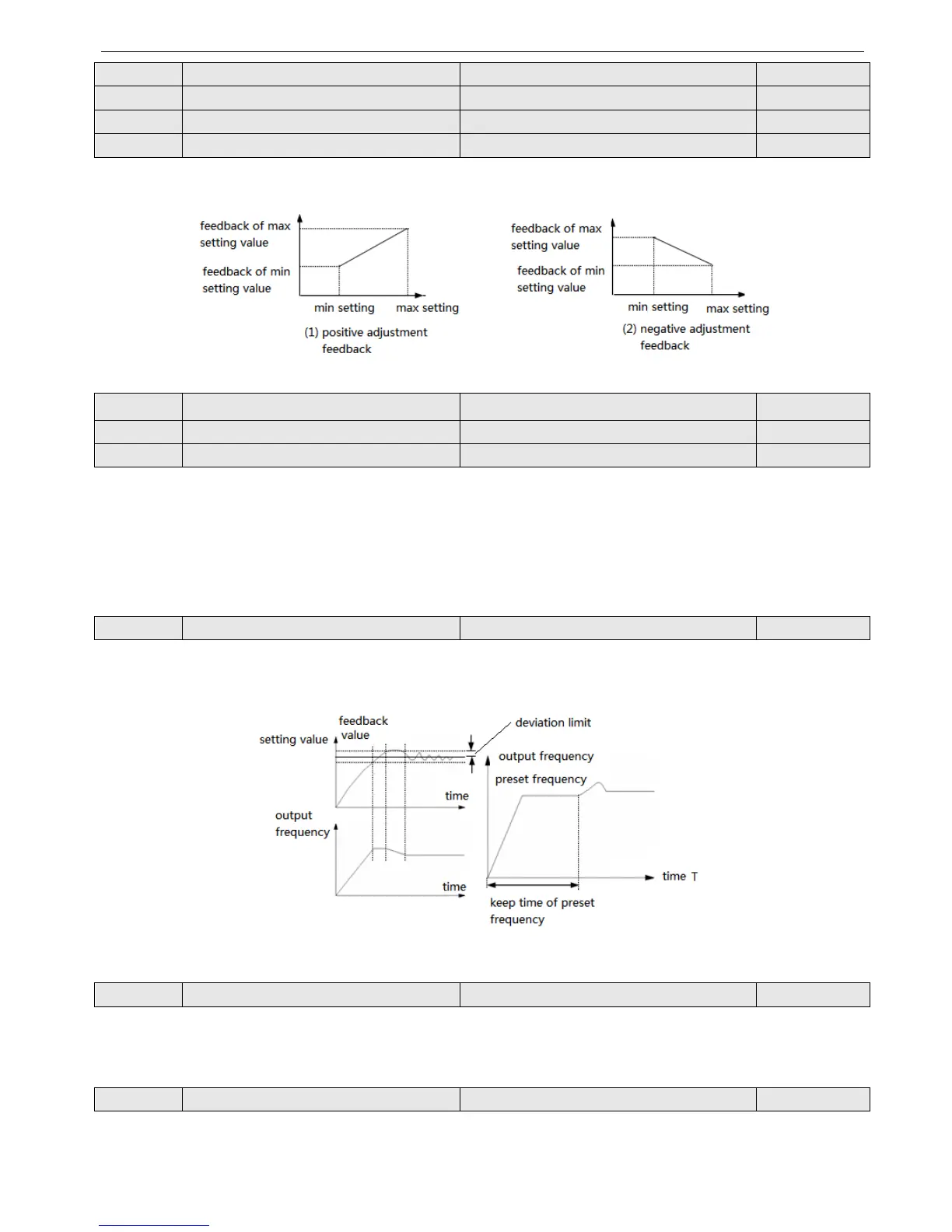
Explains parameters for setting up and tuning the closed-loop control system.

9. Simple PLC Operation Parameters (Group P8)

Covers parameters for the inverter's integrated simple PLC functionality.

10. Swing Frequency Function Parameters (Group P9)

Details parameters for configuring swing frequency operations, used in textile/fiber industries.

11. Vector Control Parameters (Group PA)

Explains parameters specific to vector control motor operation.

12. Special Application Function Parameters (Group PB)

Covers parameters for special application modes like fan/pump control.

13. Default Setting and Password (Group PF)

Parameters for managing default settings and user password protection.

Fault Diagnosis and Solution

5-1. Fault Diagnosis and Solution

Lists common fault codes, possible reasons, and suggested solutions for troubleshooting.

5-2. Check the Fault Records

Explains how to access and use recorded fault codes and parameters to diagnose issues.

5-3. Fault Reset

Provides methods for resetting the inverter after a fault occurs.

Maintenance

6-1. Maintenance

Outlines routine checks and general maintenance practices for the inverter.

6-2. Periodical Care and Maintenance

Details specific inspection points and countermeasures for periodic maintenance.

6-3. Warranty of the Inverter

Explains the warranty terms and conditions for the Xinje inverter.

Communication Protocol

7-1. Overview of Communication Protocol

Introduces the RS485 communication port and Modbus-RTU protocol support.

7-2. Communication Protocol

Covers networking modes and communication protocol details for connecting devices.

7-3. Modbus-RTU Communication Protocol

Describes the character structure, information, and parameters for Modbus-RTU communication.

Appendix A Accessories

A-1. Brake Resistor

Provides information on selecting and wiring brake resistors for inverters.

A-2. Operate Panel

Lists compatible operate panel models and their mounting dimensions.

A-3. Extension Cable of Operate Panel

Details available extension cable types and lengths for the operate panel.

Appendix B Function Configuration List

Related product manuals