LaserFOCUS VLF-500 Product Guide VESDA
®
6
1. Place the detector on its back, push in the securing tab and lift up the field service access
door. (See Figure 25, “Field Service Access Door security tab and clip,” on page 28).
2. Remove the 2 retaining screws and lift off the main cover.
3. Disconnect the restraining strap from the clip (C) and the ribbon cable from the user
interface card (B) and place the cover aside.
4. Open the clips (E).
5. Lift out the user interface display card, carefully turn it through 180
o
and then clip it back into
place.
6. Reconnect the ribbon cable and the restraining strap.
7. Replace the main cover and screw down the 2 retaining screws.
8. Close the field service access door.
The detector is now ready for inverted installation.
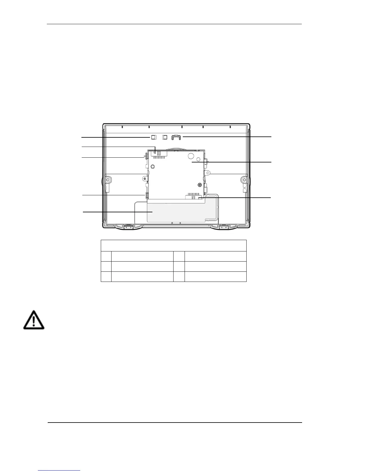
Figure 6 - Inside view of the front cover (as it would appear inverted)
Detector removal
Caution: Electrostatic discharge precautions need to be taken prior to removing the front
cover from the detector otherwise damage may occur to the unit.
Note: Take the necessary steps to advise the monitoring authority of work being carried
out and that the system needs to be disabled.
F
C
D
B
A
B
E
E
Legend
A Ribbon cable clip D Interface card
B Ribbon cable connector E Clip
C Retaining strap clip F Air filter cartridge cavity

 Loading...