VESDA
®
LaserFOCUS VLF-500 Product Guide
7
1. Turn off the power to the detector.
2. Disconnect the sampling pipes.
3. Push in the security tab and lift up the field service access door, see Figure 25, “Field
Service Access Door security tab and clip,” on page 28.
4. Unscrew the front cover retaining screws (E).
5. Lift off and swing down the front cover, a restraining strap will take the load. For inverted
mounted detectors the cover should be removed and placed aside.
6. Disconnect all field wiring from the terminal block.
7. Unscrew the two M4 x 20 mm locking screws on the left and right side of the detector. See
the items marked (F) in the Figure Detector removal on page 7
8. Use a screw driver to push down the anti-tamper clip in hole (A), at the same time, push the
detector base up.
9. Lift the detector off the mounting bracket.
Once the detector has been removed re-fit the front cover to keep the internal components safe
from damage and the electrical cabling safe.
Note: For inverted mounted detectors, the front cover will need to be removed prior to
unhooking the detector from the mounting bracket. Disconnect the retaining strap
and the ribbon cable from the user interface card and place the cover aside.
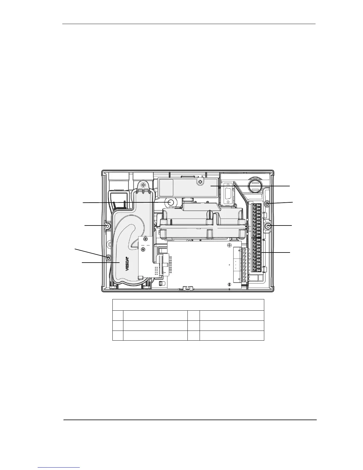
Figure 7 - Detector removal
Air inlet pipe connections
The tapered shape of the air inlet port is designed to accept standard pipes of OD 25 mm
(ID 21 mm) or IPS ¾ in (OD 1.05 in) and provide an air tight seal.
Note: Do not glue the air inlet pipe to the detector. This will void your warranty.
B
C
F
A
Legend
A Anti-tamper clip access hole D Aspirator
B Dual stage air filter cartridge E Retaining screw
C Terminal block F Bracket locking screw holes
E
E
F
D

 Loading...