VESDA by Xtralis VESDAVLSProduct Guide
www.xtralis.com 23
5 Connecting to the Pipe Network
5.1 Inlet Pipes
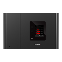
The inlets in the pipe inlet manifold are designed to receive a standard pipe of 25 mm (1 in) OD. A 25 mm to
1.050 inches adaptor to fit the pipe inlet manifold is included for all shipments to USA.
Figure 5-1: Pipe Adaptor
The design of the air inlet ports allow insertion of the sampling pipe to a depth of 15 mm. (0.60 in). This
prevents the sampling pipes from damaging the flow sensors. While connecting the detector to the pipe
network:
l Ensure a minimum length of 500 mm (19.7 in) of straight pipe before terminating the pipes at the air inlet
ports of the detector.
l Square off and de-burr the end of the sampling air pipes, ensuring the pipes are free from debris.
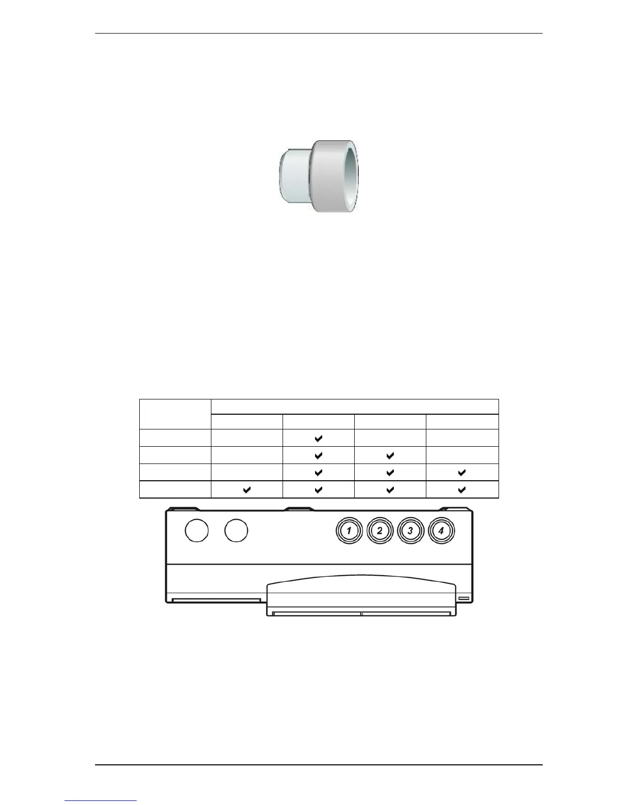
l Determine the Air Inlet Ports to be used. Refer to Table 5-1 below for details.
l Remove the plugs from only those Air Inlet Ports intended for use.
l Insert the pipes into the pipe inlet(s) ensuring a firm fit.
DO NOT glue the inlet pipes to the pipe inlet manifold. When configuring the detector ensure that the correct
pipes in use are selected.:
No. of Pipes Preferred Pipe Inlet Port to use
Pipe 1 Pipe 2 Pipe 3 Pipe 4
1
2
3
4
Table 5-1: Preferable use of pipe inlet ports
Figure 5-2: Pipe inlet port numbering

 Loading...