VESDA by Xtralis VESDAVLSProduct Guide
www.xtralis.com 25
6 Wiring Connections
6.1 Termination Card
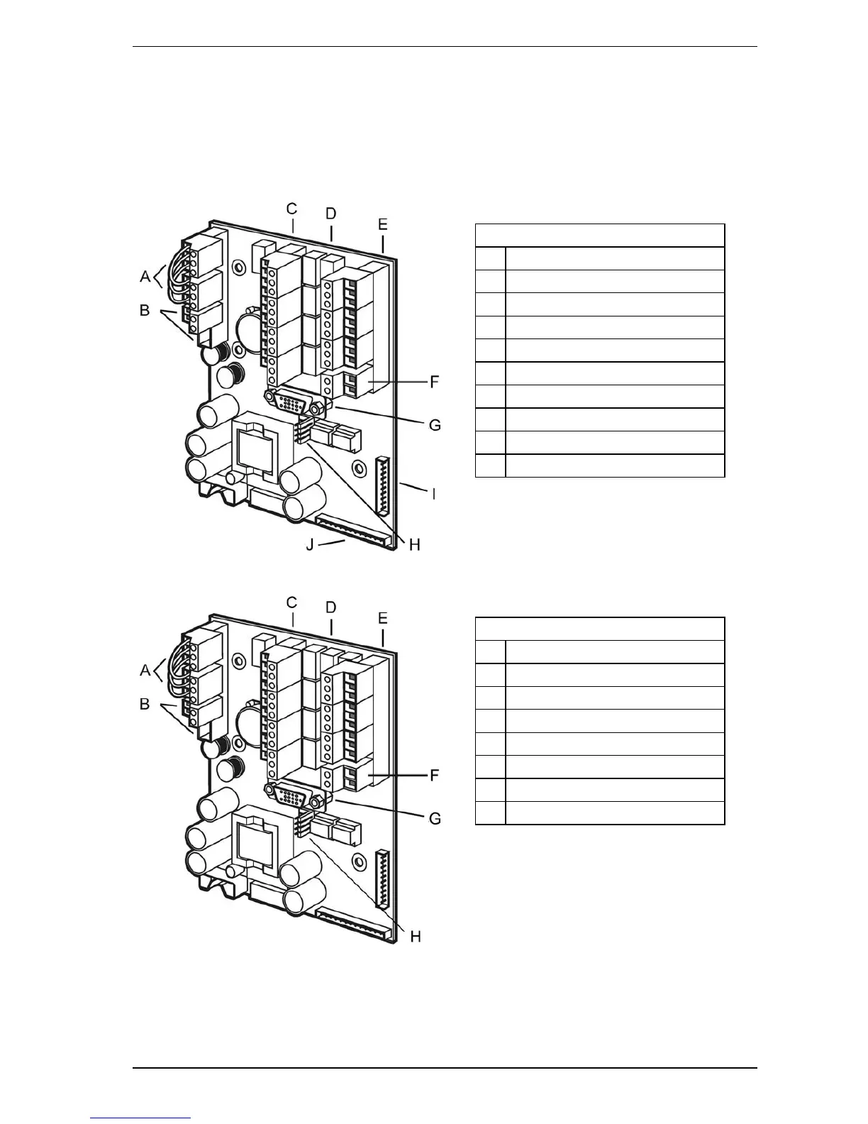
The termination card acts as the interface for VESDAnet, power supply, relays and the General Purpose Input
(GPI). The VESDA VLS is available with a 7 or a 12 Relay termination card.
Legend
A VESDAnet terminals
B Power terminals
C Relay terminals (1 to 4)
D Relays (1 to 7)
E Relay terminals (5 to 7)
F GPI terminal
G VESDAnet socket
H FOK LED connectors
I Relays cable
J Termination cable
Figure 6-1: Termination Card
Legend
A VESDAnet terminals
B Power terminals
C Relay terminals (3,1,2,4,5, and 7)
D Relays (1 to 12)
E Relay terminals (8,9,10,11,12 and 6)
F GPI terminal
G VESDAnet socket
H FOK LED connectors
Figure 6-2: Optional 12 relays terminal card illustrating relays and termination points

 Loading...