VESDAVLSProduct Guide VESDA by Xtralis
40 www.xtralis.com
11.2 Internal Wiring for the VESDA VLS
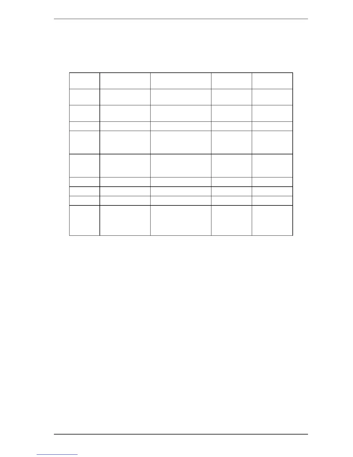
The table below provides the cable loom interconnecting details inside the detector. Use the look up table in
conjunction with the attached circuit diagram to assist with maintenance.
From To Connector card and
CPU card
Cable Name # Pins
CPU card Scanner connector
on scanner valves
Scanner or X4 Scanner cable 10
CPU card Scanner connector
on sensor card
Flow sensor or X5 Flow sensor
cable
10
CPU card Filter Switch Card Filter switch or X12 Fail SW 5
CPU card Termination or X1
connector on
termination card
Termination or X1 Termination 13
CPU card Relays or X2
connector on
termination card
Relays or X3 Relays 10
CPU card Detection chamber Pre-amp or X9 Pre Amp 6 Wire ribbon
CPU card Detection chamber Laser or X10 Laser 6
CPU card Aspirator Aspirator or X11 5
CPU card Term or X1
connector on
programmer or
display
Expansion or X2 11
Table 11-2: VESDA VLS Internal Wiring
Notes:
l Do not disconnect the cable running between the CPU card and the detection chamber.
l All connectors are polarized and can only be inserted one way into its socket.
Do not attempt to force the connector into its socket. If there is any difficulty, reverse the orientation of the
connector before inserting again.

 Loading...