VESDAVLSProduct Guide VESDA by Xtralis
38 www.xtralis.com
11.1 Replacing the chassis/Air Inlet Pipe Manifold
1. Isolate the VESDA VLS by pressing the Isolate button or by selecting Isolate Zone from the Zone
menu in Xtralis VSC. This isolates the outputs from the unit to a fire alarm panel and other third party
devices such as building management systems.
2. If you are using Xtralis VSC, highlight the detector in the Device Tree Window and select the Device
menu, then Save Node Configuration. This will save the configuration details of the VESDA VLS.
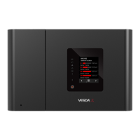
3. Remove the front panel by using a flat ended screw driver to open the cover plate (A) and screw covers
(B), then unscrew the front cover.
Legend
A Cover plate screws
B Screw covers
Figure 11-1: Removing Front Cover
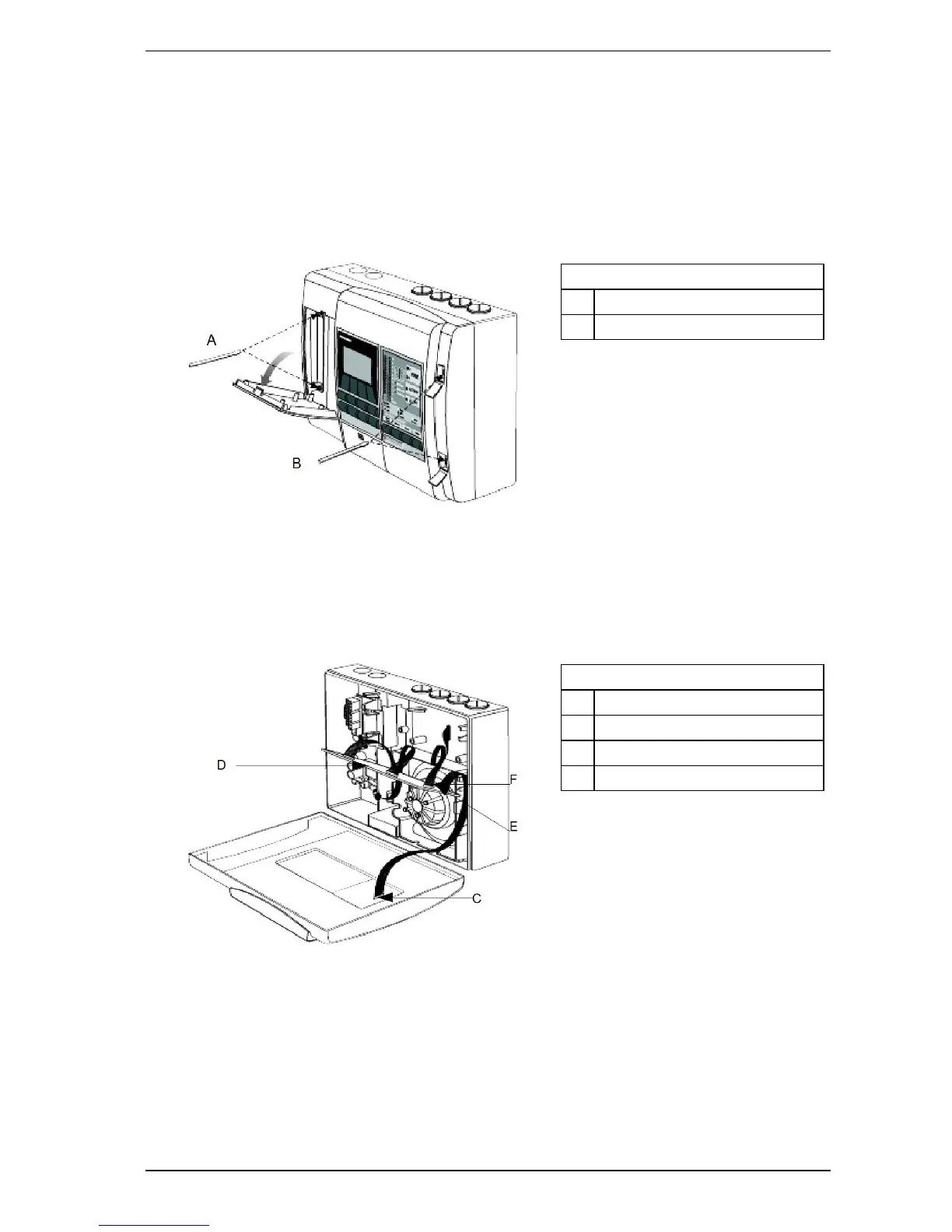
4. Either let the front cover hang on the plastic retainer straps, or take it off by disconnecting the retainer
straps and the termination cable loom where it connects to the front cover (C).
5. Turn off the power by disconnecting the power cables. Power terminals can be seen on Figure 6-1 on
page 25.
6. Unscrew the PCB head processor card (D), lift up and disconnect the flow sensor (E) and scanner (F)
cables from the card.
Legend
C Termination cable
D Head processor card
E Flow sensor cable
F Scanner cable
Figure 11-2: Remove Data cables
7. On the terminal card, disconnect the Termination and Relays cables. For details refer to Figure 6-1 on
page 25.
8. Unscrew the two manifold retaining screws (G).

 Loading...