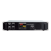
RX Receive (up link) band display area
TX Transmit (down link) band display area
Touch key display area
[BACK] Touch here to return to the operation mode screen.
[SQL] Touch here to set the squelch level of the receiver.
[Tx PWR] Touch here to set the transmitter output level.
[F] Touch here to display the setup menu.
Direction display area
“UP LINK” is displayed on the RX band.
“DOWN LINK” is displayed on the TX band.
Status display area
A green bar is displayed during receive when signals are detected.
The bar will not be displayed when the squelch is turned on.
Frequency display
VOL/SQL level display
S-meter/transmission power level display
Communication mode display
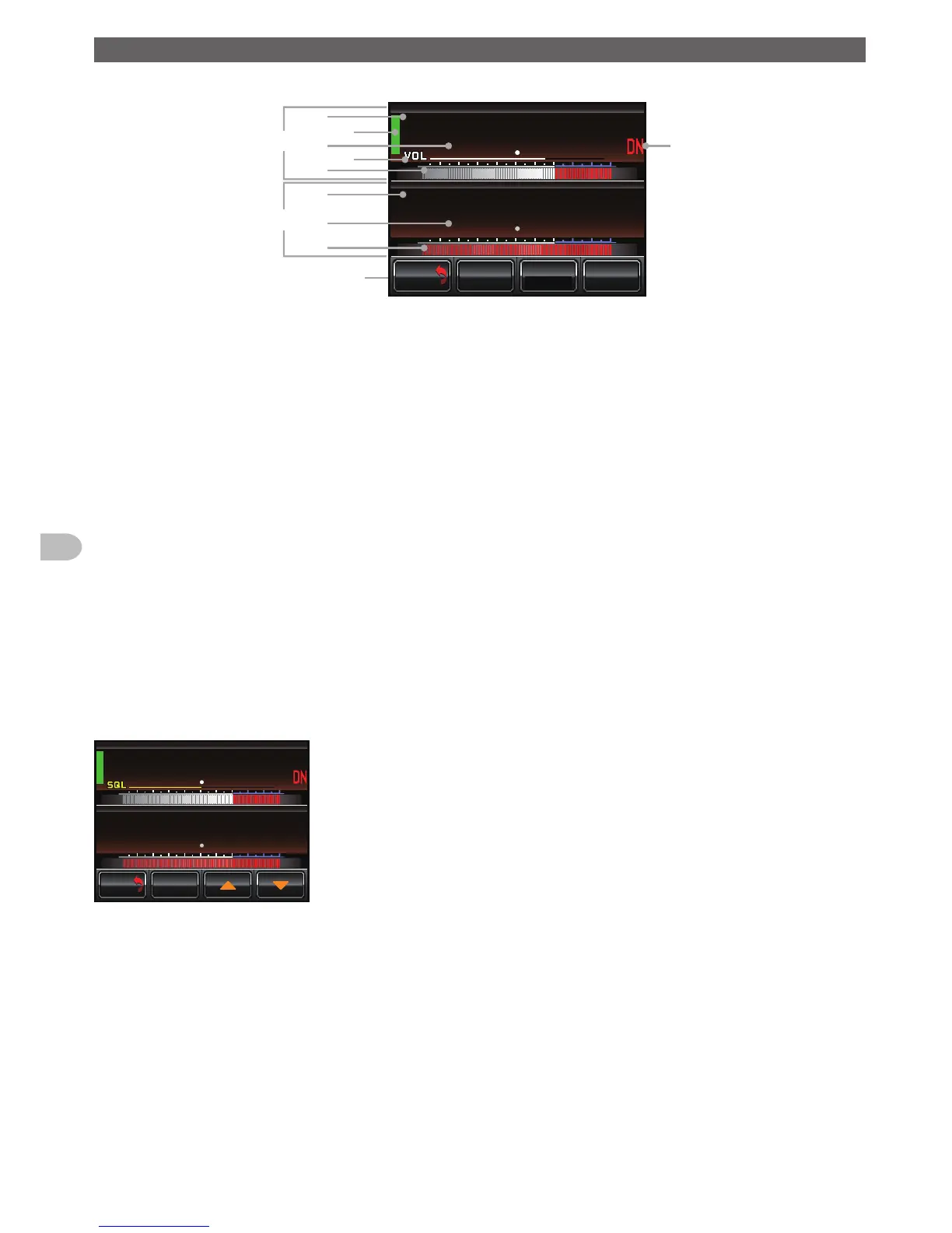
● Squelch level setting screen
The screen appears as below after [SQL] is touched.
5'672
Ჽ
Ჽ
Ჸ
Ჸ
7
2
0
-+
.
0
-+
.
Ჸ
Ჽ
Ჸ
Ჸ
&1
90
/8 53.
$#%-
$#%-
[▲][▼] Thesquelchthresholdwillincreasebytouching[▲]anddecreasebytouching
[▼].
 Loading...