Connecting External Devices
Connection to an external controller
Some optional cables can be used to connect the repeater to an external controller that allows the repeater to be controlled remotely.
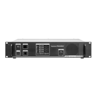
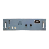
Use the [CONTROL I/O] connector at the back of the repeater to connect with the external controller.
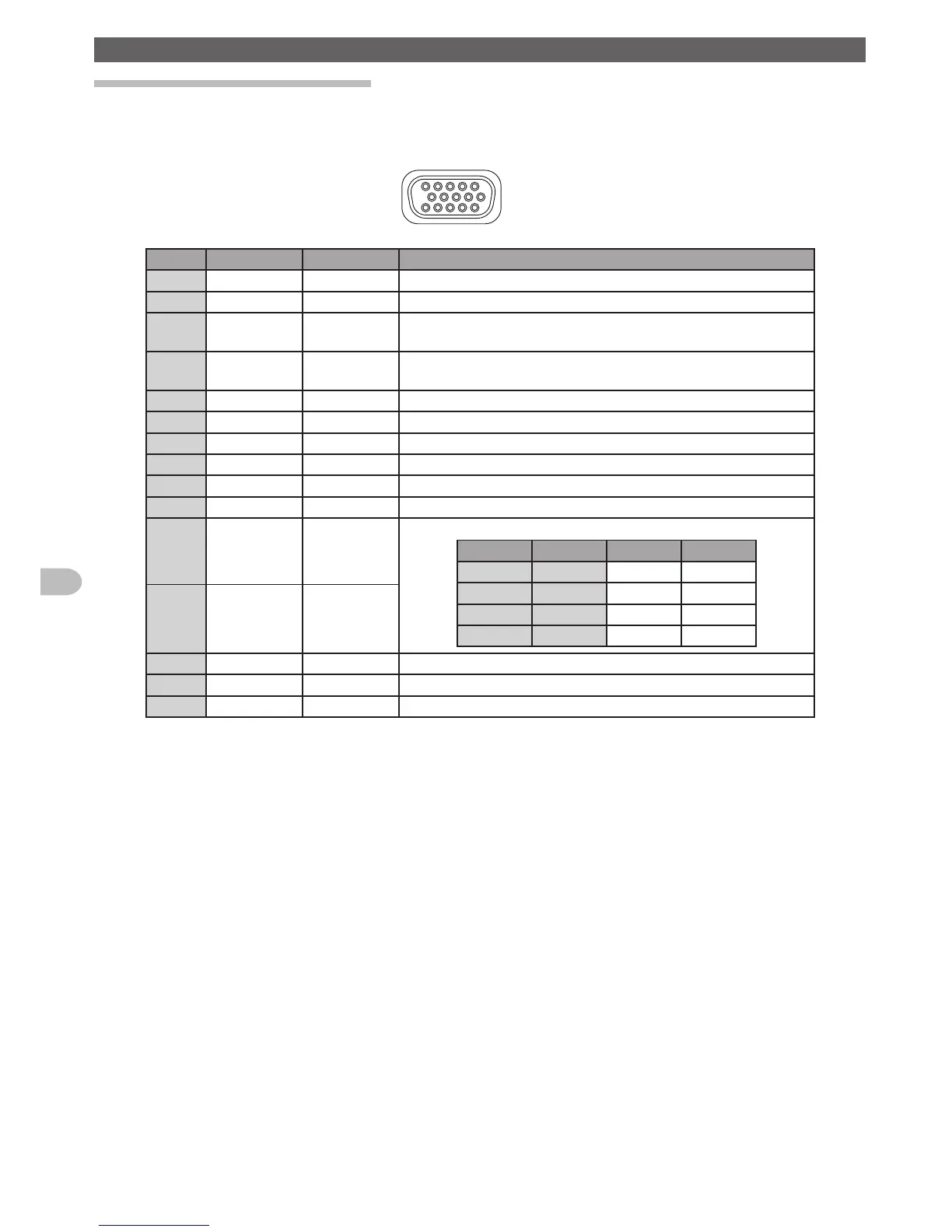
The pin assignment of the [CONTROL I/O] connector is as follows.
Pin No Pin Name I/O Operations
1 BASE I L: Base mode OPEN: Repeater mode
2 PTT*
1
I L: EXT PTT ON OPEN: EXT PTT OFF
3 CTCSS/DCS
(PKSQL)*
1
O L: Decoded OPEN: Undecoded
4 SQL DET
(Noise SQL)*
1
O L: SQL open OPEN: SQL close
5 GND GND GND
6 TONE IN*
1
I CTCSS/DCS EXT input / 600 ohm
7 AF IN*
1
I EXT Modulation input / 600 ohm
8 DISC OUT O Up-link RX Disc output (w/o de-emphasis)
9 AF OUT O Up-link RX AF output (w/ de-emphasis)
10 GND GND GND
11 EXT port 1*
2
I Determined by the signal combination of the port 1 and 2 as below:
Port 2 Port 1 RX TX
H H AUTO FM
H L FM FM
L H Digital Digital
L L AUTO AUTO
12 EXT port 2*
2
I
13 EXT port 3*
2
I L: RX Tone OFF OPEN: Setup mode
14 EXT port 4*
2
I L: TX Tone OFF OPEN: Setup mode
15 VCC VCC Switched VCC (12 V)
*1: These functions may only be activated while the repeater is in Base mode.
*2: These functions may only be activated while the repeater is in Remote mode.