EasyManua.ls Logo

Yaesu FT-890 User Manual

Yaesu FT-890
48 pages
To Next Page IconTo Next Page
To Previous Page IconTo Previous Page
Page #41 background imageLoading...
Page #41 background image
CAT
System Computer Control
variable in the program to an ASCII string, and
then to convert the string to characters through a
lookup table.
If you send a parameter that is out of range for
p
the intended function, or not among the speci-
b
fied legal values for that function, the FT-890
$
should do nothing. Therefore, you may wish to
1
alternate your sending regular commands or
I
i:
command groups with a
Read
Flags
or an
Update
i
command, allowing the transceiver to let the
computer know if everything sent so far has
been accepted and acted upon as expected.
Bear in mind that some commands specify
'%inary," as opposed to BCD-formatted parame-
ters. You can send binary parameters without
going through the
character/hex string conver-
sion process. For example, the CH parameter in
the Command table is binary. You could have the
PRINT $2, CHR$
(0)
;CHR$
(0)
;CHR$
(0)
;CHR$
(29)
;CHR$
(2)
;
Reading Returned Data
The reading process is easily done through a
loop, storing incoming data into an array, which
can then be processed after all expected bytes
have been read into the array. To read the meter:
FOR
1-1
TO
5
MDATA(1)
=
ASC (INPUT$
(I,
$2))
NEXT
I
Recall from above that the meter data consists
of four identical bytes, followed by a filler byte,
so we really only need to see one byte to get all
of the information this command offers. Never-
theless, we must read all five bytes (or
1,18,19 or
649, in the case of the Update data). After reading
all of the data, we can select the bytes of interest
FT-890 recall memory 29 (decimal) by the follow-
to us from the array (MDATA, in the above ex-
ing
:
ample).
CTCSS Tone Codes
(hex)
&
Frequencies
(Hz)
Frequency
67.0
1
127.3
1
ODh 233.6
1
1Eh
71.9
77.0
82.5
88.5
94.8
100.0
103.5
107.2
110.9
114.8
118.8
123.0
page
35
Code
00
0 1
02
03
04
05
06
07
08
09
OAh
OBh
OCh
Frequency
146.2
-
---
Code
Ilh
151.4
156.7
162.2
167.9
173.8
179.9
186.2
192.8
203.5
21 0.7
218.1
225.7
12h
13h
14h
15h
16h
17h
18h
19h
1 Ah
1 Bh
1Ch
1 Dh

Table of Contents

Other manuals for Yaesu FT-890

Question and Answer IconNeed help?

Do you have a question about the Yaesu FT-890 and is the answer not in the manual?

Yaesu FT-890 Specifications

General IconGeneral
Antenna Impedance50 ohms
Power Supply Requirement13.8 V DC ±15%
ModesSSB, CW, AM, FM
Power Output100 W
Current Consumption20 A

Summary

Meter Functions

Meter Scale Overview

Explains S, PO, SWR, and ALC meter scales used for reception and transmission.

Top Panel Control Functions

Mode Selection & Operation Switches

Covers mode buttons (LSB, USB, CW) and operation switches (POWER, MOX, VOX).

Audio, Transmitter, and I/O Jacks

Details AF/RF gain, MIC, RF PWR, and headphone/microphone jacks.

Front Panel Controls

VFO & Memory Management

Explains VFO/M, A/B, SPLIT, M-VFO buttons for frequency and memory operations.

Tuning, Scanning, and Locking Features

Covers CLAR, TUNER, BAND/MEM, DOWN, UP, FAST, and LOCK functions.

Meter Functions Detailed

Reception and Transmission Metering

Provides detailed explanations of S-meter, PO-meter, SWR, and ALC scales.

Top Panel Controls Detailed

CW Keyer & Break-in Operation

Explains KEYER switch, BREAK-IN, and SPEED adjustment for CW.

Display Indicators and Information

Operational Mode & Tuning Indicators

Describes indicators for SPLIT, VFO, GEN, M TUNE, FAST, NAR, CLAR, and frequency display.

Status and Error Indicators

Explains HI SWR, WAIT, and memory scan skip status indicators.

General Description

FT-890 Overview and Design

Summarizes the transceiver's features, design, and performance.

Installation Guidance and Manual Use

Offers advice on installation and effective manual usage.

Specifications

General and Transmitter Specs

Lists general specs (freq ranges, modes) and transmitter performance metrics.

Receiver and Antenna Tuner Specs

Details receiver sensitivity, selectivity, IF parameters, and antenna tuner options.

Accessories & Options Overview

Supplied Accessories and Antenna Tuners

Lists included accessories and details optional ATU-2/FC-800 antenna tuners.

Optional Oscillators and Loudspeakers

Covers TCXO-3 stability oscillator and SP-6 loudspeaker.

Accessories & Options Continued

Digital Voice Recorder & CAT Interface

Explains DVS-2 voice recorder and FIF-232C CAT system interface.

Headphones & IF Crystal Filters

Describes YH-77ST headphones and optional IF crystal filters.

Accessories & Options Continued

Microphone Options and Response

Details MH-1B8 and MD-1C8 microphones, features, and audio response plots.

Station Installation Guide

Inspection, Power Supply, and Ventilation

Covers initial inspection, AC power setup, and ensuring adequate transceiver ventilation.

Grounding, Panel Angle, and Antenna Setup

Guides on proper grounding, front panel angle adjustment, and antenna setup.

Station Installation Guide

Mobile Power and Mounting Procedures

Details mobile power connection, safety, and bracket mounting.

Mobile Antenna and Grounding

Applies antenna principles to mobile installations, focusing on grounding.

Station Installation Guide

Accessory Interconnection & Memory Backup

Explains connecting accessories and the function of the memory backup lithium battery.

Connector Pinouts

Data, Tuner, and Audio Jacks Pinouts

Details pin assignments for BAND DATA, TUNER, CAT, DVS-2, DATA IN/OUT, PHONES, RCA jacks.

Keyer and Speaker Jacks Pinouts

Explains pinouts for KEYER PADDLE, EXT SPKR, and STRAIGHT KEY connectors.

Connecting External Accessories

Linear Amplifier Connection Diagrams

Illustrates connection diagrams for linear amplifiers like FL-7000 and non-QSK types.

Connecting a Linear Amplifier

ALC & T/R Switching for Linears

Guides on ALC connection and T/R switching, covering QSK and non-QSK setups with linears.

Power-Up Customization & Button Combinations

Power-Up Function Settings

Lists functions adjustable by holding buttons during power-up (beeper, display, etc.).

FAST Button Combination Settings

Describes settings adjusted using FAST button combinations, like display brightness and tuning rate.

Operation - Getting Started

Initial Setup & Basic Controls

Guides on initial setup, identifying controls, and basic power-on procedures.

Tuning, Scanning & Band Selection

Explains frequency tuning, scan steps, and amateur band selection.

Operation - Interference Handling

Frequency Display & General Reception

Covers displaying 10-Hz digit, general coverage tuning, and band recall behavior.

Interference Suppression Features

Details IPO, ATT, RF Gain, and Noise Blanker settings for reducing interference.

Beeper Settings Adjustment

Explains how to adjust the front panel beeper's enable/disable and pitch.

Operation - Interference Handling

RF Gain, AGC, Noise Blanker & IF Shift

Guides on optimizing RF gain, AGC-F, noise blanker, and IF Shift for clear reception.

IF Filters & Control Locking

Details using AM/CW narrow filters and locking controls to minimize interference.

Operation - Interference Handling

IF Shift & SSB Crystal Filter Tuning

Covers fine-tuning IF Shift and installing/using the YF-101 SSB crystal filter.

AM/FM Frequency Steps & IF Notch Filter

Explains 10-Hz steps in AM/FM, using the IF Notch filter, and heterodyne suppression.

Operation - Transmitting

Basic Transmitting & Antenna Matching

Covers transmitting procedures, SWR monitoring, and automatic antenna matching.

SSB Transmission Setup

Guides on setting up SSB transmission, including MIC, RF PWR, and VOX.

Operation - Transmitting

Processor Frequency Shift & Tone Selection

Details adjusting IF processor shift and selecting microphone tone characteristics.

AF Speech Compressor Adjustment

Explains activating and adjusting the AF speech compressor for improved signal quality.

Operation - Transmitting

VOX Operation Setup & Controls

Guides on setting up VOX for transmit/receive switching and adjusting its parameters.

CW Transmission Modes & Keyer Connections

Explains CW transmission types, break-in modes, and connecting CW keyers.

Operation - Transmitting

Internal Keyer, Sidetone & AM/FM Transmission

Covers internal keyer, sidetone volume, and settings for AM/FM transmission.

Operation - Digital Modes

FM Repeater Operation & Clarifier Use

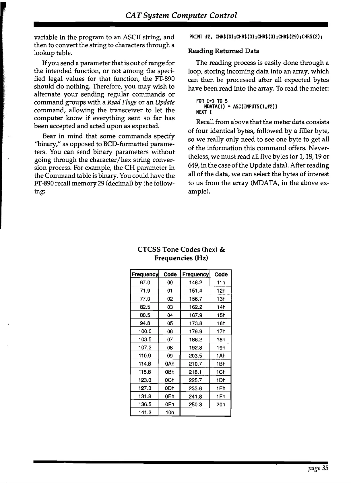
Explains FM repeater functions like offset, CTCSS tones, and Clarifier tuning.

VFO B & Split Frequency Operation

Details using VFO B for storage and split frequency transmit/receive operations.

Operation - Digital Modes

Split Frequency Storage & Tuning Knob Adjustment

Guides on storing split frequencies and adjusting the tuning knob torque.

Memory Features

Memory Storage & Checking

Explains storing frequencies/modes into memories and checking their contents.

Memory Features

Memory Recall, Tuning & Clarifier Management

Covers recalling memories, memory tuning mode, and managing clarifier settings.

Memory Features

Memory Scanning, Skip & Blanking

Details scanning memories, skipping specific ones, and blanking unwanted memories.

Subband Limit Memories P1 & P2

Explains using P1/P2 memories to define subband limits for scanning and tuning.

Memory Features

Subband Limit Memory Examples

Provides practical examples of using memories P1 and P2 to set subband limits.

Digital Modes

TU/TNC Interconnections for Digital Modes

Guides on connecting TUs/TNCs for digital mode operation.

Digital Modes

Transmitter Adjustment & Frequency Tuning for Digital

Covers transmitter adjustments and frequency tuning specific to digital modes.

Digital Modes

1200-Baud FM Packet Operation

Details setup and operation for 1200-baud FM packet communication.

Optional DVS-2 Digital Voice Recorder

Receiver & Transmission Recording Functions

Explains DVS-2's capabilities for recording receiver audio and microphone voice messages.

CAT System Computer Control

CAT Commands Structure & Data Return

Introduces CAT commands, data return types, and data organization.

Data Returned From FT-890

Explains types of data returned by the transceiver (Status Update, Flags, Meter).

Status Update Data Organization

Describes the structure of the 649-byte Status Update data.

CAT System Computer Control

VFO, Memory Data Records & Status Selection

Details VFO/Memory data formats and how to select specific status data.

CAT Command Examples & Data Reading

Provides examples of CAT commands and procedures for reading returned data.

CAT System Computer Control

CAT Command Examples & Data Reading

Continues with practical examples of CAT commands and reading transceiver data.

Installing Internal Accessories

Cover Removal Procedures

Guides on removing transceiver covers to access internal components for installation.

Installing Internal Accessories

TCXO-3 Enhanced-Stability Oscillator Installation

Details the installation process for the TCXO-3 oscillator option.

Installing Internal Accessories

Local Unit Connector Color Codes

Provides a reference for wire colors and connector pin assignments for the Local Unit.

Installing Internal Accessories

IF Crystal Filter Installation

Guides on installing optional IF crystal filters for enhanced receiver selectivity.

ATU-2 Internal Antenna Tuner Installation

Details the installation steps for the ATU-2 internal antenna tuner.

Rear Panel Overview

Rear Panel Connectors & Controls

Describes all rear panel connections, including DC power, antenna, audio jacks, and control ports.

Related product manuals