11
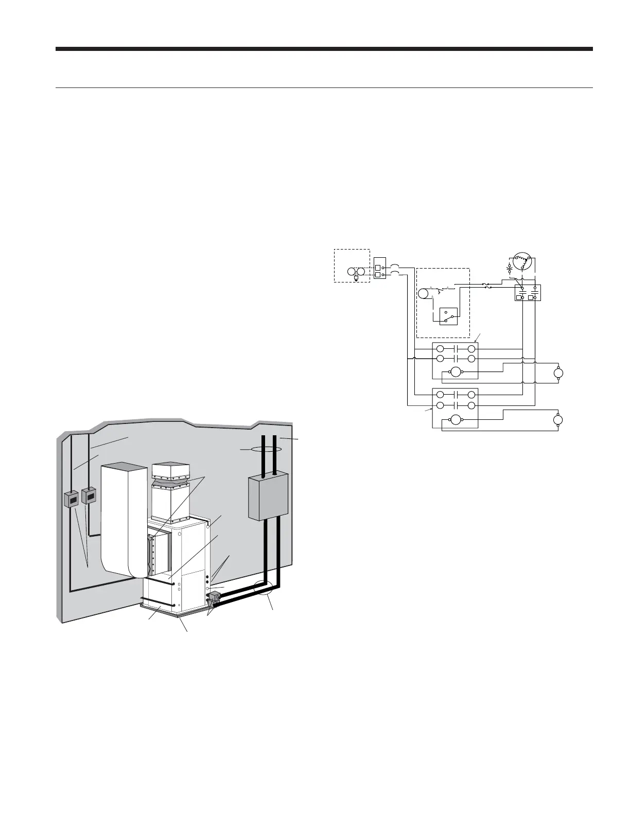
Figure 7: Closed Loop Ground Source Application
Once piping is completed between the unit, pumps and
the ground loop, final purging and charging of the loop
is required. A flush cart (or a 1.5 HP pump minimum) is
needed to achieve adequate flow velocity in the loop to
purge air and dirt particles from the loop itself. A filter
MUST be used when flushing a loop. The standard 100
micron filter bag (LFC-F100M) is acceptable for capturing
relatively large debris such as pipe shavings, gravel, and
medium sand particles. In certain installation locations
other smaller materials such as fine sand, silt, and clay
can be less than 75 microns. For these smaller particles
the use of the 1 micron filter bag is required (LFC-F1M).
It is also recommended to run the flush cart with the
1 micron filter bag for at least 30 minutes. Antifreeze
solution is used in most areas to prevent freezing. Flush
the system adequately to remove as much air as possible
then pressurize the loop to a static pressure of 40-50 psi
(summer) or 50-75 psi (winter). This is normally adequate
for good system operation. Loop static pressure will
fluctuate with the seasons. Pressures will be higher in
the winter months than during the cooling season. This
fluctuation is normal and should be considered when
initially charging the system.
Flexible Duct
Collar
Vibration Absorbing Pad
P/T Plugs
Drain
Hot Water Generator
Connections
Auxiliary
Heater
Knockout
Low
Voltage to
Thermostat
Unit Supply
Auxiliary Heat
Supply
Insulated piping
or hose kit
Disconnects
(If Applicable)
Unit Power
P/T
TO
LOOP
GeoLink
®
Flow
C
enter
GeoLink
®
Polyethylene w/
Armaflex
®
Insulation
NOTE: Additional information can be found in Flow Center
installation manual and Flush Cart manual.
Closed Loop Ground Source Systems
Figure 8: Primary/Secondary Wiring with Aurora Base Control
(no AXB Board)
CC
T2
T1
Compressor
C
R
S
Blue
L1
L2
Black
Red
Ta n (6 )
Cap
Ext Pump
1/2 hp Total
208-230/60/1
Pump
G
1
2
PB1
1
2
Pump
Circuit
Breaker
Circuit
Breaker
1
5A
5A
Optional Internal
HWG Pump
HWG
Pump
Purple
Hot Water
Limit Switch
130°F
Blue
1
2
3
Cabinet
HW Switch
Field Supplied
Relay for Heat
Pump 1
Field Supplied
Relay for Heat
Pump 2
Heat Pump 1
Contactor Coil
Heat Pump 2
Contactor Coil
Field Supplied
Fuses 5A
Multiple Units on One Flow Center
When two heat pumps are connected to one loop pumping system,
follow figure 8. Installer will be required to supply fuses, two relays,
and wiring. It is recommended that water solenoid valves
be installed on heat pumps that share a flow center. This is
to allow water flow through only the heat pump that has
a demand. Circulating fluid through a heat exchanger of a
system that is not operating could be detrimental to the
long-term reliability of the compressor.
LX SERIES INSTALLATION MANUAL
 Loading...