28
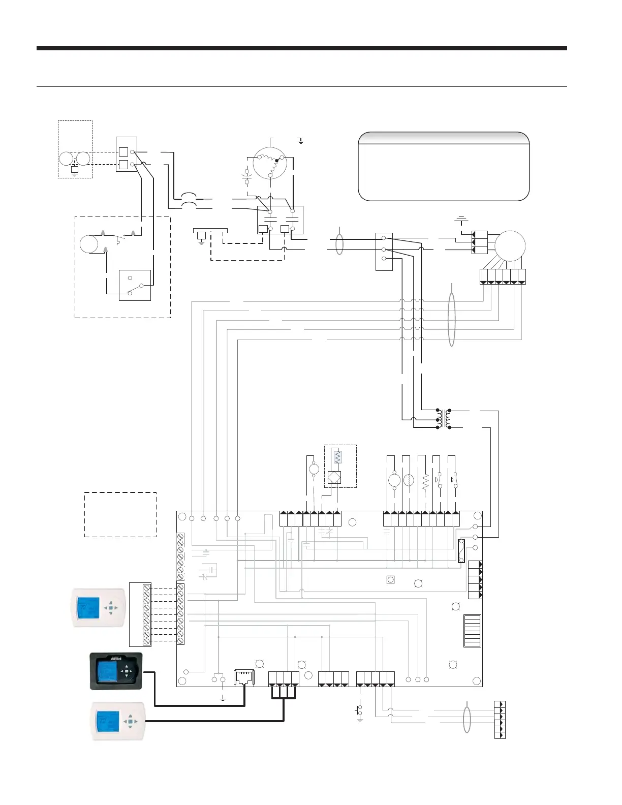
Wiring Schematics
Aurora BASE with 5-Speed ECM
Tra nsf ormer
24V
To P 2 on
El ec t r ic H e at
Board
RV
CC
HP
Condensate
Black
Black
Blue
Blue
LP
T
Yellow
Yellow
FP1
Orange
Orange
RV
Black(15)
Violet(14)
Green(11)
Brown(23)
NOTE 1
Black/White
Yellow
Red
208V
1 C
24
3 2
Black(21)
Black(20)
PB2
1
3
2
Blue
240V
Black
UltraTech
Dual Capacity
Units Only
RCP
CS
Blue(16)
Blue(18)
CC
T2 T1
Compr essor
C
R
S
G
L1L2
Black
208-230/60/1
Unit Power Supply
Violet(7)
Tan(6)
Black(3)
Black(2)
Cap
Ext Pump
1/2 hp Total
208-230/60/1
Pump
G
1
2
PB1
1
2
Pump
Violet(8)
NOTE 2
Gray/White(4)
Black/White(5)
Ther mos tat
R
C
Y1
O
DH
Y2
G
W
LO
Circuit Breaker
Circuit Breaker
OpƟonal Internal
Hot Water GeneraƟon P ump
1
5A
5A
DHW
Pump
Blue
Hot Water
Limit Switch
130°F
Blue
1
2
3
Purple
Traditional
Thermostat
Communicating
Thermostat
AID Tool
Cabinet
HW Switch
123
LNG
C45
Green
Orange
Brown
Gray(30)
Tan (31)
Red(32)
Blue(33)
Black(35)
NOTE 3
NOTE 4
Tan(6)
Black
Blue
Black(22)
5 Speed ECM
Blower Motor
Black
CFM
P13
P4
SW1
P5
JW2
P9
LO
O/B
Y2
W
DH
P8
P7
RS485 NET
RS485 NET
P6
RS485 EXP
P3
SW2
On
Fut ure U se
L Output Type
CC – Dual/Single
Acc – Dip 5
Acc – Dip 4
RV – B/O
FP2 – 15°F/30°F
FP1 – 15°F/30°F
Com1
LED5
Com2
LED5
Tes t Mod e
F1-3A
P1
C
PWM
1
2
3
4
5
6
7
8
ALM
ALG
ACC COM
ACC NO
ACC NC
R
C
G
Y1
EH2CEH1
C
CO
C
R
-
+C
R-+
Of f
Faul t
LED1
R
Status
LED3
Config
LED2
CC2
CC
F
C
R F FG CC CCG
CC2
HI
CC2
LO
CC2
G
RE VREV FP 1 FP 1 FP 2 FP2 LP S LP S HP SHP S
Aurora Base Control
(ABC)
K1-RV Relay
K2-CC Rel ay
K3-CC2 Relay
K4-Fan Relay
K5-Alarm
Relay
K6-Acc
Relay
F
R
C
CCGY1
C
R
ES
LS
P2
EH1
Y
G
G
G
Water Solenoid
(see Open Loop
Groundwater Systems
secƟon)
470
470
Resistor
Black
Red
Gr een/Ye llow
Notes
1 - Switch blue a nd red wires f or 208V operat ion.
2 - The blk/wh and gray/wh wires are removed when Aux He at is installed
3 - Refer to units X13 MOTOR LOW VOLTAGE CONNECTION table for factory settings.
4 - Wires provided fo r Auxiliary Heat low voltage control. When connected the Auxiliary Heat
powers blower and controls. Wires a re secured at blower.
5 - Field installed SPST relay required for dual fuel installation.
6 – All low voltage wi ri
ng CLASS 2
7 – Use copper o r aluminum conductors
LX SERIES INSTALLATION MANUAL
 Loading...