16
R
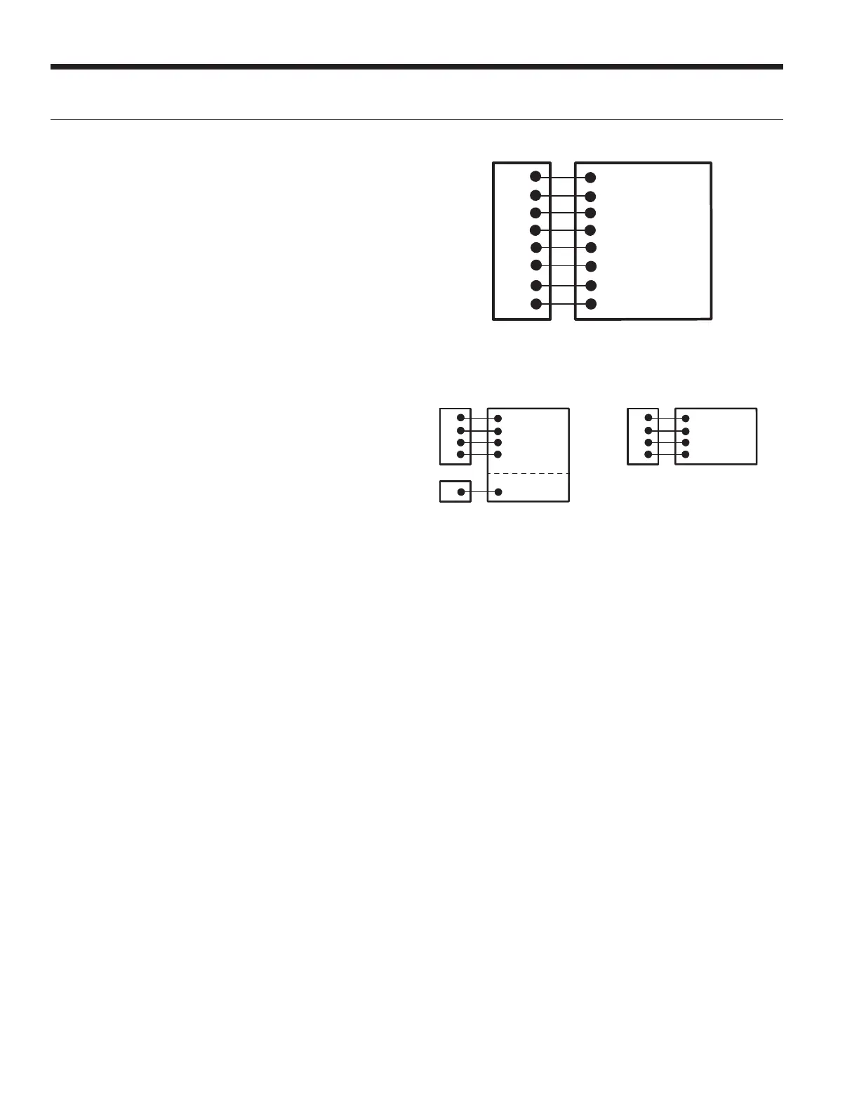
Y1
C
W
O
G
L
24VAC (Hot)
24VAC (Common)
Compressor (1st Stage)
Aux. Heat
Reversing Valve
Blower Relay
System Monitor
Heat Pump Connection
Thermostat Connection
Y2
Compressor (2nd Stage)
Electronic Thermostat Installation
Figure 15a: Thermostat Wiring (Y1 Style Signals)
Figure 15b: Thermostat Wiring (Communicating Style Signals)
LX SERIES INSTALLATION MANUAL
C
P7
P1
–
R
W
C 24VAC (Common)
R 24VAC (Hot)
B- Communication
W1 (Optional)
Heat Pump Connection
Thermostat Connection
+
A+ Communication
TPCM32U03AYRK/TPCM32U04AYRK
Monochrome Thermostats
C
P7
–
R
C 24VAC (Common)
R 24VAC (Hot)
DX- Communication
Heat Pump
Connection
Thermostat
Connection
+
DX+ Communication
TPCC32U01YRK
Color Touchscreen
Thermostat
Position the thermostat subbase against the wall so that it is
level and the thermostat wires protrude through the middle of the
subbase. Mark the position of the subbase mounting holes and
drill holes with a 3/16-inch bit. Install supplied anchors and secure
base to the wall. Thermostat wire must be 8-conductor (4 or 5
counductor for communicating thermostats), 20-AWG (minimum)
wire. Strip the wires back 1/4-inch (longer strip lengths may
cause shorts) and insert the thermostat wires into the connector
as shown. Tighten the screws to ensure secure connections.
The thermostat has the same type connectors, requiring the
same wiring. See instructions enclosed in the thermostat for
detailed installation and operation information. The W1 terminal
on TPCM32U03AYRK and TPCM32U04AYRK communicating
thermostats may be hard wired to provide aux/emergency heat in
the event communication is lost between the thermostat and the
ABC microprocessor.
NOTE: Aurora Base Control (ABC) DIP switch SW2-7 is
required to be in the “OFF” position for the control to operate
with FaultFlash or ComforTalk thermostats. SW2-7 in the “ON”
position configures the control to operate with typical thermostats
(continuous lockout signal). There must be a wire connecting
Y2 on the Aurora controller to 2nd stage compressor on the
thermostat for proper operation. SW2-7 DIP switch position is not
relevant with communicating thermostats.
 Loading...