505428-YTG-V-0417
8 Johnson Controls Unitary Products
• Safety lockouts provide reset capability at the space
thermostat or base unit should any of the following
standard safety devices trip and shut off compressor:
a. Loss-of-charge/Low-pressure switch.
b. High-pressure switch.
c. Control board diagnostics and fault message display.
d. Safety lockouts send a 24 volt signal to the control
board's "X" terminal, allowing notification to the user
via the thermostat fault light (if present).
e. In the unlikely event any faults should occur, the unit
control board will store the faults in its internal
memory. The LCD display will scroll the 5 MOST
critical faults, however, all fault messages can be
extracted via USB device, displayed real-time via the
MAP Gateway as well as be broad-casted through a
BAS system (if applicable). The UCB will provide fault
messages in plain English to ensure the user can
easily understand the specific fault.
Non-fused Disconnect Switch
• Factory-installed, internally mounted.
• Accessible from outside the unit.
• NEC and UL approved non-fused switch.
• Provides power off lockout capability.
Convenience Outlet
• Factory-installed, internally mounted.
• Accessible from outside the unit.
• 115V, 15 amp GFI receptacle with independent fuse
protection.
• Required voltage provided by factory-installed step-
down transformer or field supplied 115v circuit.
Low-ambient Head Pressure Control
• Standard operation down to 40 °F without a low
ambient kit.
• Operation down to 0°F with a field-installed low ambient
kit accessory. The controller modulates the fan motor
speed in response to liquid line temperature or
pressure.
Coil Guard
Factory or field installed decorative grille shall be placed on
the units to protect condenser coil after installation.
Hail Guard Package
Field installed hail guard package shall protect coils against
damage from hail and other flying debris.
Coated Condenser Coils
Special phenolic or epoxy polymer coating available as a
factory option on both outdoor and indoor coils.
Each Unit Shall Be:
• Covered by a 1-year limited parts warranty on the
complete unit and 5-year on compressor(s).
• In current production with published literature available
to check performance, limitations, specifications, power
requirements, dimensions, operation and appearance.
• Indoor unit shall be equipped with a V-belt drive option
that will permit the blower RPM to be adjusted to meet
the CFM requirements of the air delivery system. (Refer
to Technical Guide for Airflow Capabilities.)
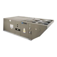
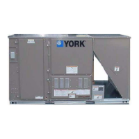
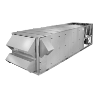
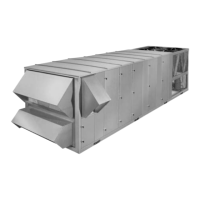
Each Unit Enclosure Shall Have:
• Exterior panels of 18 gauge steel, finished with baked
enamel to provide a long lasting quality appearance
• Removable panels to provide easy access to the
internal components for maintenance and service on
condensing units, heat pumps and air handlers
• Air handling units must have a filter rack that accepts
both 2” and 4” filters (7.5 - 20 Ton only).
• The dimensions of each unit shall not exceed those
specified in the manufacturers literature.
• The minimum application clearances for condensing
units, heat pumps and air handlers must meet those
specified in the manufacturer’s literature.
The Blower Motor Shall:
• Be mounted within the insulated cabinet to minimize the
transmission of sound to the surrounding space, and
any motor 7.5 HP or greater must have a service factor
of 1.15.
IntelliSpeed discrete fan control shall:
• Control fan speed with a VFD (Variable Frequency
Drive)
• Drive fan speed based on the number of cooling or
heating stages.
• Maximum airflow on first stage cooling not to exceed
67%.
The Evaporator Coil Shall:
• Consist of copper tubes arranged in staggered rows,
mechanically expanded into aluminum fins,
• Be draw-through, and
• Include factory-mounted distributors, expansion valves
and solenoid valves for capacity reduction.
The Blower Wheels Shall:
Be dynamically balanced to minimize the levels of sound and
vibration generated by the unit.
 Loading...