3 Installation
26 | 266 MODBUS® multivariable transmitter User manual 2105216 Rev. AB
6. Insert the probe and head assembly through the bottom half of the union previously installed onto the thermowell. As union
halves meet, the probe should encounter some resistance from the spring. As the probe contacts the bottom of the
thermowell, the top of the probe should rise a maximum of ¾".
IMPORTANT NOTE: The probe should extend into the center 1/3 of the stream. If the probe assembly is too
long (the top of the conduit union will not screw into the bottom half of the conduit union) or too short (no
resistance is encountered when screwing the probe and head assembly into the bottom half of the union), then
the nipple fitting may need to be replaced with one of a different length.
7. Align the RTD head to correspond with the wiring conduit previously installed and complete the connection.
8. Tighten all conduit and fittings to wrench tight.
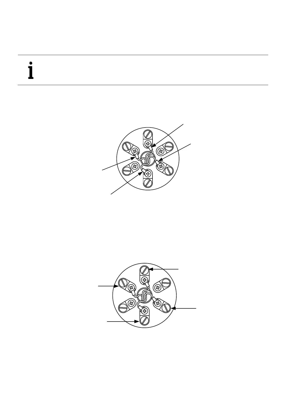
9. Wire the RTD probe wiring to the wiring block located inside of the explosion-proof head assembly (Figure 21).
Figure 21: RTD probe wiring to explosion-proof head wiring block
10. Remove the shipping plug from the transmitter housing.
11. Remove the rear housing cover from transmitter if not already removed (go to section 5.2, Transmitter hardware security
for additional instructions).
12. Install the conduit or cable gland and wire from the RTD explosion-proof head to the transmitter.
13. Connect the transmitter wiring to the RTD wiring block (Figure 22).
White wire to
transmitter
Black wire to
transmitter
Black wire to
transmitter
White wire to
transmitter
Figure 22: RTD wiring to transmitter
14. Screw the RTD cover onto the explosion-proof housing assembly to complete the RTD installation.
15. Use the procedure in section 5.10, RTD wiring verification, to verify that the RTD to transmitter cable is in good working
condition or not damaged during installation.
White probe wire
Red probe wire
Red probe wire
White probe wire