5 Service and maintenance
266 MODBUS® multivariable transmitter User manual 2105216 Rev. AB | 57
Replacing the RTD probe
The following procedure provides steps to replace the RTD probe in the transmitter.
WARNING – Bodily injury. When the housing covers are removed and power is still connected, there is a
potential for explosion. Failure to observe this safety information may result in death or severe injury.
Do not remove housing covers in hazardous (classified) areas or explosive environments unless the area is
known to be non-hazardous. Verify an explosive atmosphere is not present before removing the housing covers
when power is live.
This procedure does not require the transmitter to remain powered up.
1. Disconnect power to the transmitter.
2. Use the instructions in section 5.2.1, Removing the housing cover, to remove the rear housing cover, exposing the terminal
block.
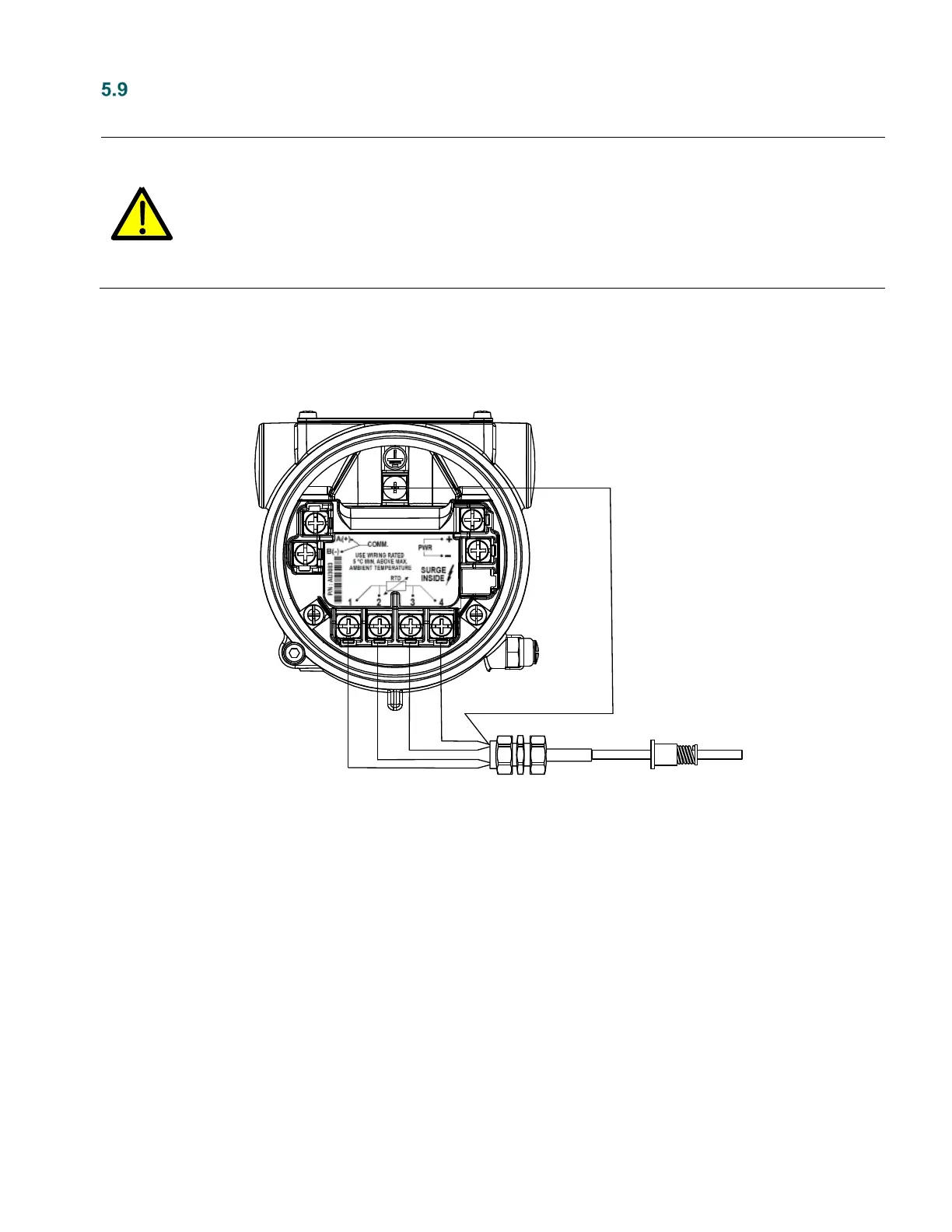
3. Disconnect all RTD termination wires from the terminal block (Figure 46).
Figure 46: RTD replacement
4. Install the new RTD.
5. Reconnect all RTD wires to the terminal block.
6. Replace and secure the rear housing cover (go to section 5.2.2, Securing the housing cover).
7. Reconnect power to the transmitter.
8. Verify that the device configuration is correct and that the LCD is displaying correctly.
RTD Probe
WHT
WHT
BLK
BLK
Shield

 Loading...


