Appendix C MODBUS® register lists
86 | 266 MODBUS® multivariable transmitter User manual 2105216 Rev. AB
Appendix C MODBUS
®
register lists
All registers in this document are referenced to base one. The MODBUS
®
message frame for read and write access is base zero.
This means that the number of the mapped register is one higher than the number that is sent in a MODBUS
®
message frame.
Function code 4 is meant to access the process parameters, which possibly could be polled in a low cycle time (> 100 ms).
Therefore the data of the parameters is held in an internal buffer, which has a low access time. Function code 3 should be used to
access parameters that are non-cyclic or with a high cycle time (> seconds).
By reading or writing 32 bit or 16 bit registers, 4 or 2 byte are transmitted. If a parameter has a data type which uses fewer bytes
than that, the data is transmitted in the lower data bytes of the MODBUS
®
message frame. The data bytes that are not used are set
to zero.
C.1 ABB transmitter register map
This register map is an expanded map from the ABB 267 MODBUS
®
transmitter.
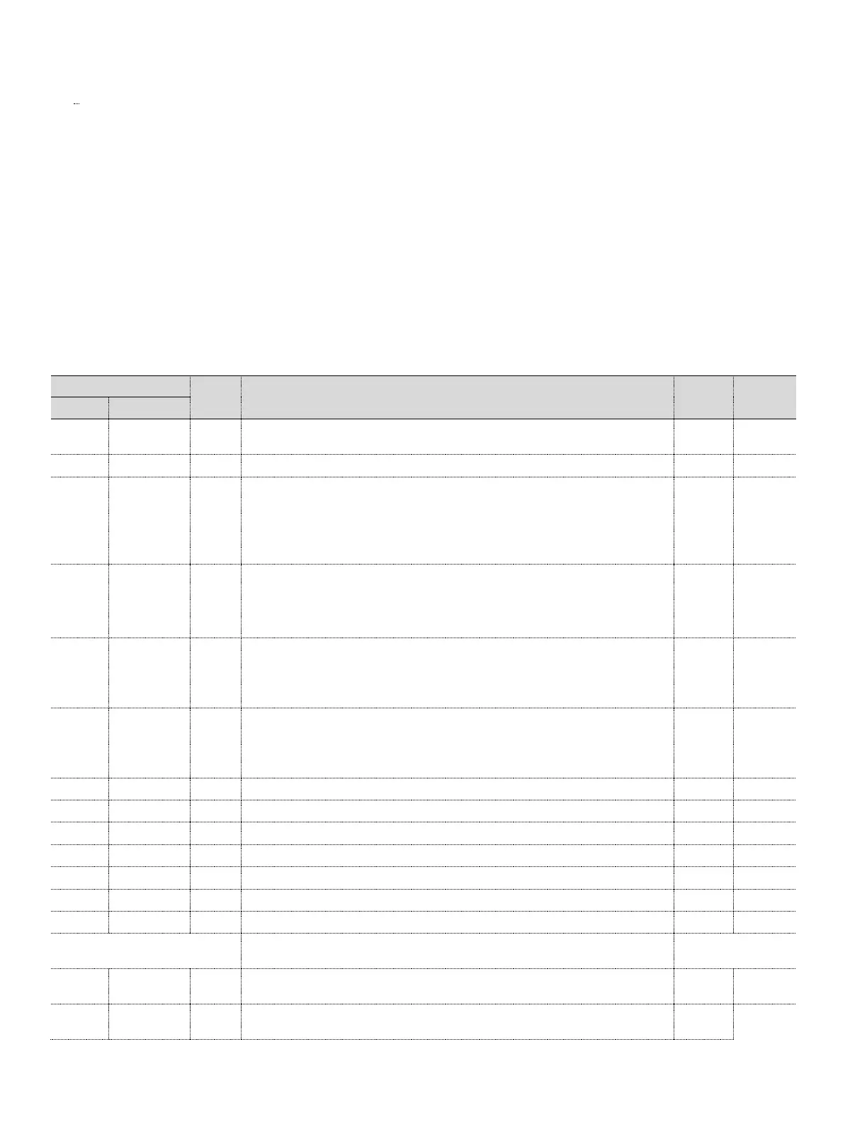
Table 20: ABB transmitter register map
Transducer ID / Serial number 16 ASCII characters string.
Ex. "T090100001" (See 4.3.1.1, Set MODBUS
®
device address, page 38)
Date Factory Characterized seconds since 1970 Jan 1st
Communication Board Hardware
example value 0x00010203 represents 1.2.3
bits 23-16 = Major Revision (compatibility change)
bits 15-8 = Minor Revision (functionality or operation)
bits 7-0 = Sub-minor Revision (bug fixes)
Sensor Board Hardware
base part number 3 MSB
version number 1LSB
see register 10 for more information
Communication Board firmware
base part number 3 MSB
version number 1LSB
see register 10 for more information
Sensor Board firmware
base part number 3 MSB
version number 1LSB
see register 10 for more information
DP Upper Range Limit (Set by Measurement Sensor URL)
DP Lower Range Limit (Set by Measurement Sensor LRL)
SP Upper Range Limit (Set by Measurement Sensor URL)
SP Lower Range Limit (Set by Measurement Sensor LRL)
Transducer cell Temperature Upper Range Limit (URL)
Transducer cell Temperature Lower Range Limit (LRL)
Second since last Restart
Normal Operation Polling registers
Differential Pressure (Damping, Calibration and Units applied ) floating point, 401
is high word, 402 is low word
Static Pressure (Damping, Calibration and Units applied ) floating point, 403 is high
word, 404 is low word

 Loading...


