Interfaces Section 3 Modules
28 M&I – AC 900F Controller
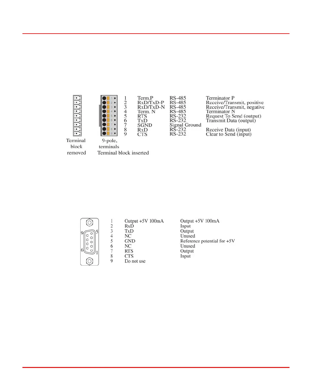
configured (and provided with termination resistors) for RS-232 or RS-485 and
used for Modbus RTU and telecontrol protocol as per IEC 60870-5-101 (depending
on the terminals used). For more detailed information on the wiring of the series
interfaces, please refer to Section 6, Wiring.
SER
Serial interface_ser1_ser2_us.png
Diagnostic interface
The third DIAG interface is provided to connect a PC for diagnostics/setting
purposes. In addition, a radio clock for time synchronization can be permanently
connected to this interface.
DIAG
Diag_interface_us.png
A TK 890F/891F diagnostic cable is required to connect the DIAG serial interface
with the serial interfaces of the PC. The default transmission rate is 19.2 kBit/s but
can be changed to 9.6 kBit/s (see Controller configuration via terminal program on
page 97).
Coupler bus
The PM CPU module features two C1/C2 coupler bus slots for the connection of
additional communication interfaces, e.g. CI/CM PROFIBUS modules.

 Loading...


