Section 3 Modules CP-C switch-mode power supply units and accessories
M&I – AC 900F Controller 49
CP-C switch-mode power supply units and accessories
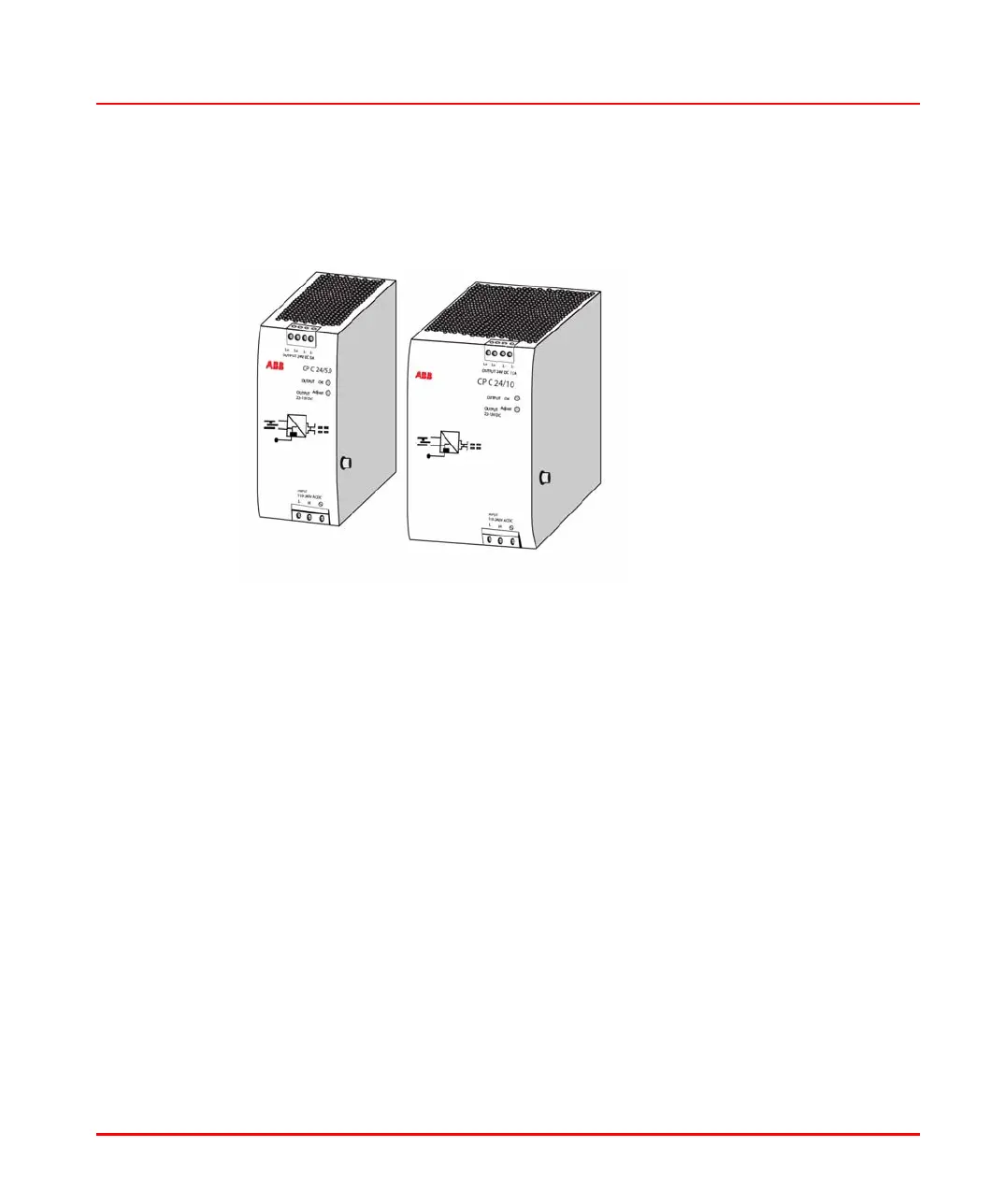
Switch-mode power supply units CP-C 24/5.0 and CP-C 24/10.0
CP-C 24.png
General description
Operating status display
The green “OUTPUT OK“ LED lights up during operation.
Adjustment of the output voltage
Using the “OUTPUT adjust“ potentiometer, the output voltage can be adjusted
within the range of 22 to 28 V.
Parallel operation
In order to increase capacity or to ensure redundancy, devices of the same type can
be connected in parallel. To ensure symmetric current distribution, the line
connections should feature identical cross-section and length.

 Loading...


