LED display and control elements Section 3 Modules
30 M&I – AC 900F Controller
Up to 10 TU I/O terminal blocks (one block per I/O module) can be added to the
CPU module. For this purpose, the I/O terminal blocks are equipped with a male
connector on the left and a female connector on the right side.
LED display and control elements
LEDs and switches
The LEDs on the front panel show essential status information and diagnostic data.
The operating mode can be changed using the switches.
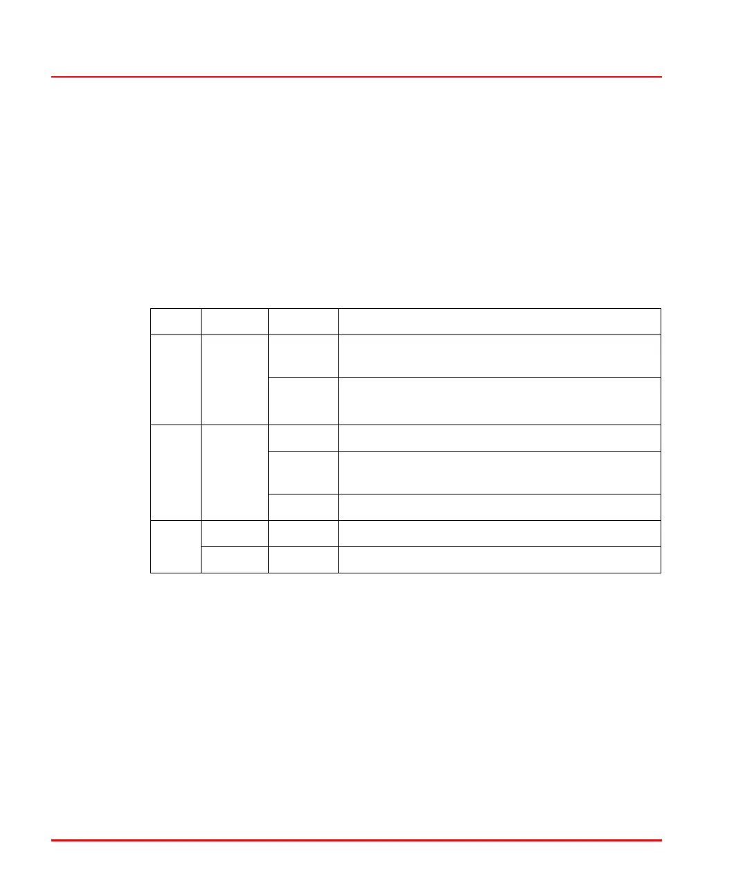
LED Color Status Meaning
PWR Green ON Power supply correctly connected, 24V DC voltage
is applied
OFF No supply voltage
Power supply not correctly connected
ERR Red ON Hardware error during self-test
Flashing Error occurred, LED continues to flash until the sys-
tem is stopped or started again
OFF No error
RUN Green ON AC 900F is operating RUN
Red ON AC 900F was stopped STOP

 Loading...


