Section 3 Modules LED display and control elements
M&I – AC 900F Controller 31
Three switches are provided for the following functions:
–RUN/STOP
– TOGGLE (Primary/ Secondary)
– RESET
RUN/STOP switch
This switch is used to start and stop the program sequence. In redundant mode, the
position of the RUN/STOP switch on the active AC 900F is used.
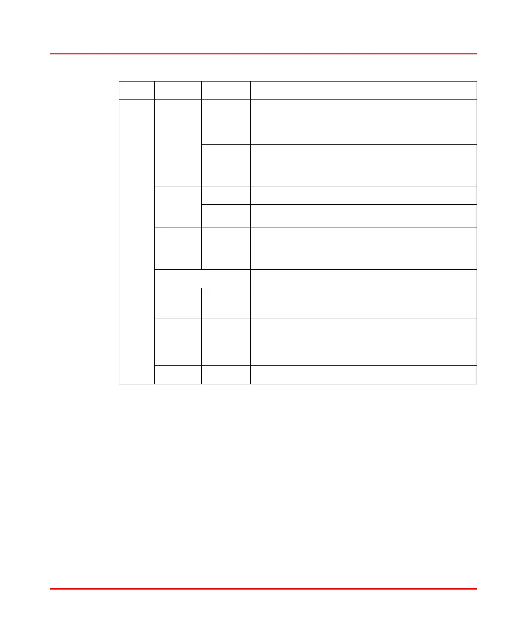
P/S Green on
Primary
ON In redundant configurations, the active AC 900F is
referred to as Primary.
Synchronous operation as normal state
Flashing Non synchronous operation as transition state; oc-
curs when the data are not aligned with the Sec-
ondary
Orange
on Sec-
ondary
ON Synchronization mode
Flashing Synchronization on
Red on
Second-
ary
ON Redundancy synchronization failed
OFF No redundancy configured
BATT Green ON Sufficient battery capacity for the indicated buffer-
ing time
Red ON Battery test during power-up
Empty battery
Battery not connected
Orange ON The battery must be replaced.
LED Color Status Meaning

 Loading...


