Bus termination Section 6 Wiring
90 M&I – AC 900F Controller
Bus termination
Serial interfaces of the CPU module
Interface standards
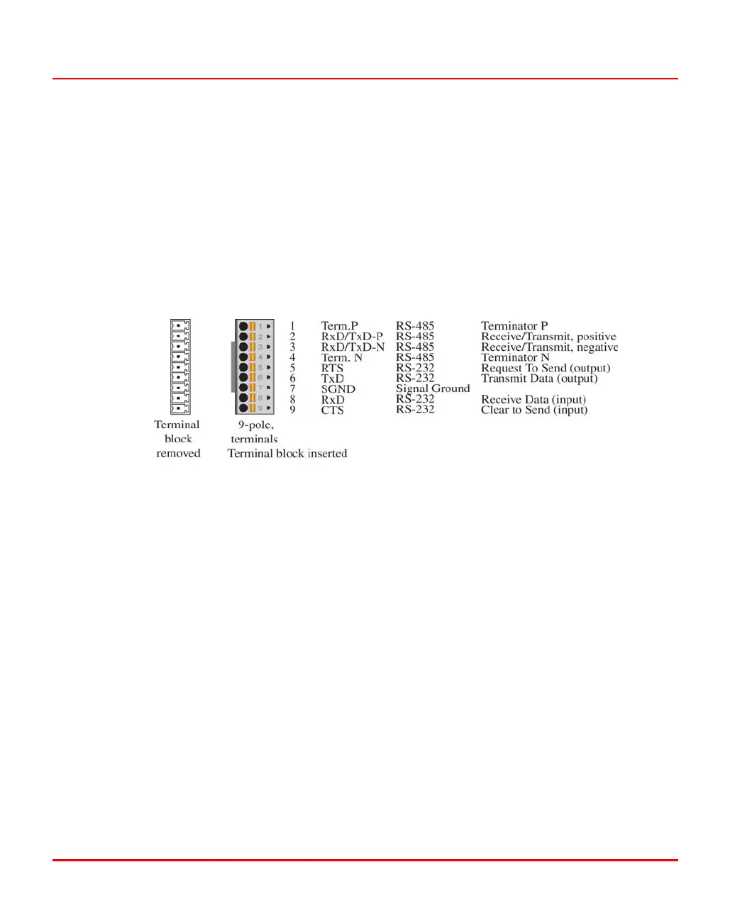
Serial interfaces comply with the EIA RS-232 and EIA RS-485 standards.
Serial interfaces (SER1 and SER2) for the CPU module
Serial interface_ser1_ser2_us.png
The SER1, SER2 serial interfaces are connected by means of a removable 9-pin
terminal block. They can be configured for RS-232 or RS-485 and used e.g. for
Modbus (master / slave).
If the RS-485-bus is used, each connected bus line (each bus segment) must be
electrically terminated. This includes:
• one 120 Ohm bus terminating resistor on both wire ends (to avoid signal
reflections).
• one additional 470 Ohm pull-up resistor on RxD/TxD-P and one 470 Ohm
pull-down resistor on RxD/TxD-N per bus. These two resistors are designed to
ensure a defined high level on the bus when no data are transmitted.
• shielded twisted-pair cables with an impedance level of 100 to 120 Ohm.

 Loading...


