Chapter 2 – Mechanical Installation
2-2 ACS/ACC/ACP 601 Frequency Converters
Installation in a
Cooling Air Duct
The ACx 601 design allows the unit to be recessed into a wall with the
cooling section protruding into a special cooling air duct (frames R2 to
R6). The cooling air grates in the bottom and the top of the unit must
not be blocked by the wall or any other structure. Steps should be
taken to enable service and maintenance for the unit.
The air in the cooling duct must meet the requirements stated for
ambient air. If the air in the cooling duct is not clean the enclosure class
of the ACx 601 must be IP 54. Note the power ratings of the IP 54
units.
To install the ACx 601 in a cooling air duct, carry out the following
steps:
1. See
Appendix B – Dimensional Drawings
for dimensions of the
opening in the duct.
2. Make the opening.
3. Mark the locations for the four holes. Drill the holes.
4. Frame R2 and R3: Undo the two screws at the lower front edge of
the unit. Lift the front cover somewhat and disconnect the Control
Panel cable from the board fitted on the inside of the cover. Remove
the front and top covers.
5. Frames R4 to R6: Remove the Control Panel. Remove the
telephone connector. Undo the two screws at the lower front edge of
the unit. Remove the front and top covers.
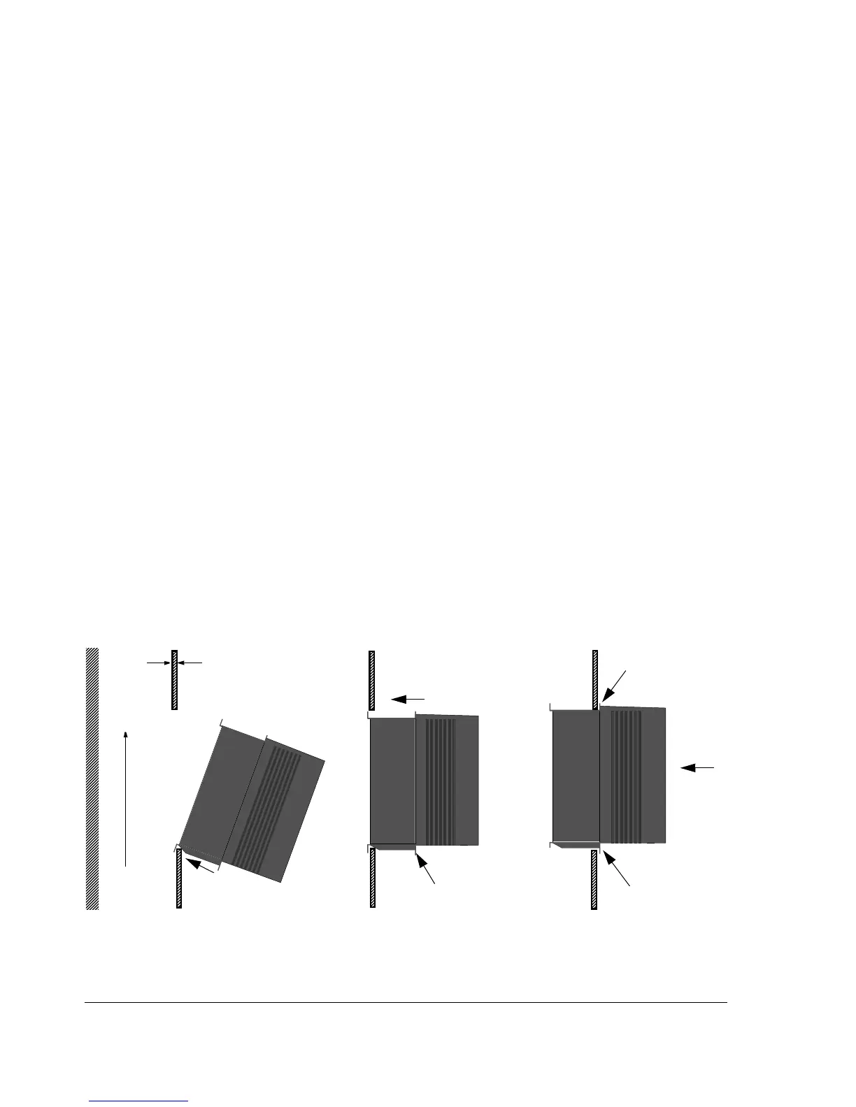
6. Follow the installation procedure in Figure 2-2.
Figure 2-2 Installation procedure of the ACx 601 in a cooling air duct.
Step 1
Step 2 Step 3
Lower screws first
Upper screws
Air
flow
out
Air
flow
in
Mounting flange
Max 10 mm

 Loading...