03 POWER ELECTRONICS AND CABINET FEATURES
3BHS213401 E01 REV H ACS1000 AIR-COOLED USER MANUAL 38/184
3.4.7 Inverter
The compartment contains the inverter and the DC-link capacitors and filter capacitors.
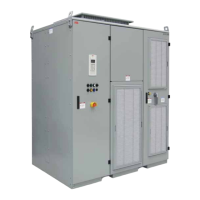
The inverter converts the DC voltage to the required AC motor voltage and frequency.
Each phase of the three-phase inverter consists of a combination of four IGCTs and two NP
diodes for three-level switching operation. The output is switched between positive DC
voltage, neutral point (NP) and negative DC voltage. Hence, the drive can control the output
voltage and the frequency continuously from zero to maximum using direct torque control. For
more information, see “4.2.2.4 Direct torque control” on page 58.
Figure 3-8: Three-level voltage source inverter principle
3.4.8 Filter
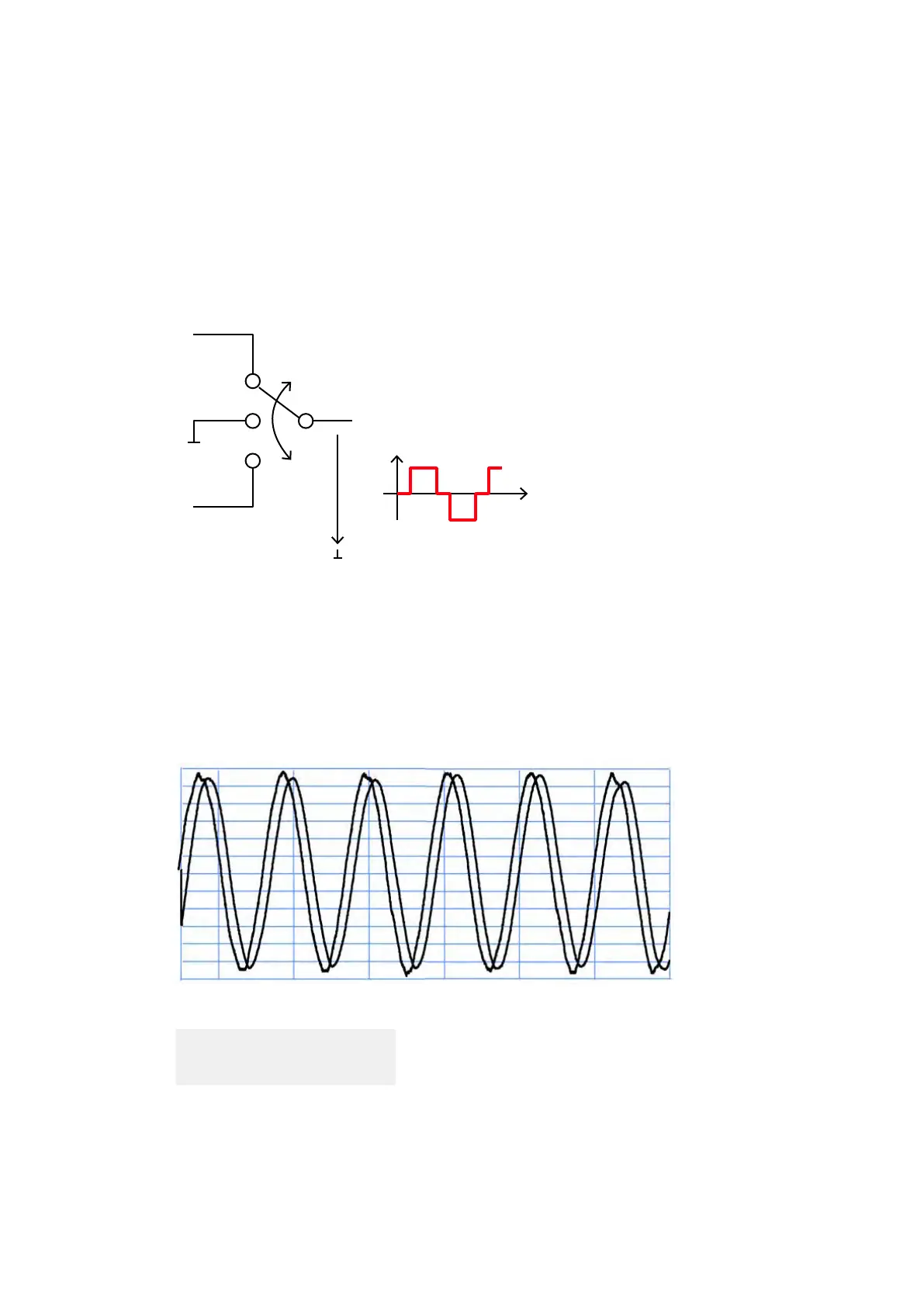
The filter at the drive output reduces the harmonic content of the motor voltage and generates
a nearly sinusoidal motor-friendly voltage waveform. The filter also eliminates all high dv/dt
effects. Therefore, standard motors can be used, and voltage reflections in the motor cables
are eliminated.
Figure 3-9: Voltage and current waveforms at drive output
3.4.9 Optional Braking Chopper
The optional braking chopper uses resistor braking to provide motor braking and shorter
deceleration times, eg, for:
Output voltage: 4.16 kV
Output frequency: 60 Hz

 Loading...