04 CONTROL SYSTEM
3BHS213401 E01 REV H ACS1000 AIR-COOLED USER MANUAL 61/184
4.3 I/O interfaces
4.3.1 IOEC I/O modules
Internal and external, analog and binary I/O signals are connected to the control system by
IOEC modules.
The standard I/O includes one external module (IOEC 2, IOEC 3) and one module that is internal
to the drive operation (IOEC 1). The standard I/O provides standard control and supervision
functionalities sufficient for most applications.
The drive can include an optional expansion I/O that includes an external module (IOEC 4).
These expansion modules provide extra inputs and outputs for control and supervision as may
be required by the drive or the customer to support various control options.
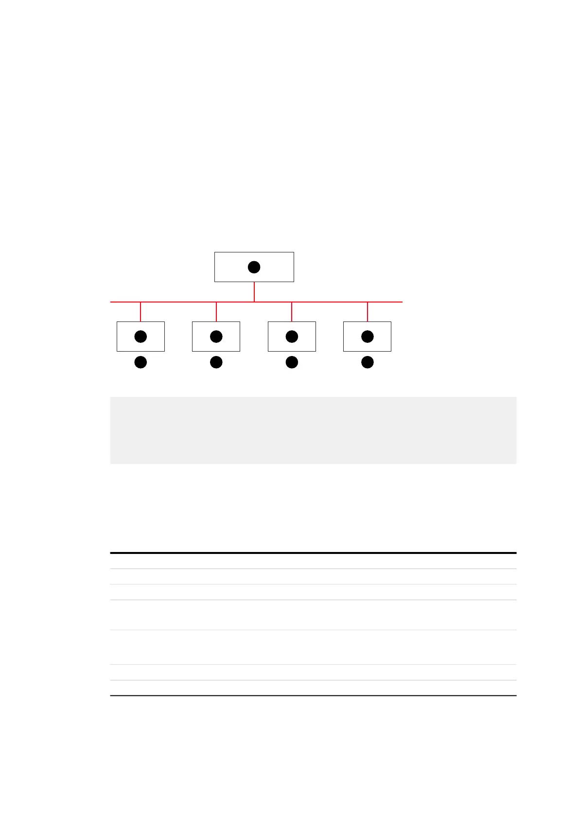
Figure 4-7: IOEC interfaces overview
4.3.1.1 IOEC module configuration
Each IOEC module is configured with both analog and digital inputs and outputs as shown in
Table 4-1, Table 4-2, Table 4-3 and Table 4-4.
Table 4-1: IOEC module configuration - analog inputs
(1) IOEC 1
(2) IOEC 2
(3) IOEC 3
(4) IOEC 4
(5) AMC circuit board
(6) Standard
(7) Option
1
2 3 4
5
6 6 7 7
No. of I/O 4
Resolution 10 bit
Signal interface Floating, galvanically isolated
Signal level 0 - 20 mA, 4 - 20 mA, 0 - 10 V, 2 - 10 V
Individually scalable by parameter
Input resistance
R
in
= 105 Ω for current input
R
in
= 250 k Ω for voltage input
Common mode voltage Maximum: 48 V
Isolation level 350 V (AC)

 Loading...