Electrical installation
66
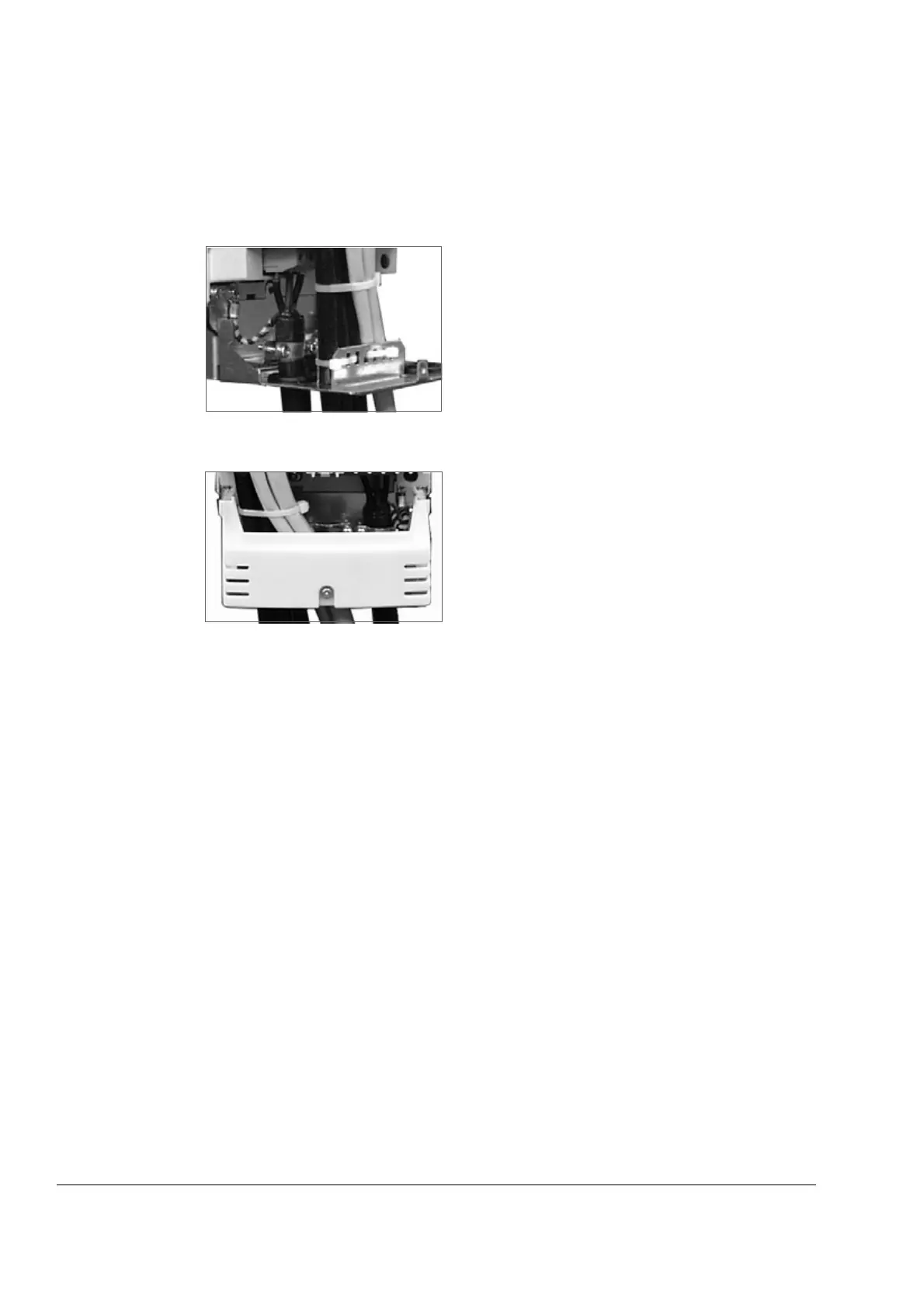
Fastening the control cables and covers
When all control cables are connected, fasten them together with cable ties. Units
with a connection box: fasten the cables to the entry plate with cable ties. Units with
a gland box: tighten the clamping nuts of the cable glands.
Fasten the connection box cover.
Replace the front cover.
Installation of optional modules and PC
The optional module (such as fieldbus adapter, I/O extension module and the pulse
encoder interface) is inserted in the optional module slot of the RMIO board (see
Connecting the control cables) and fixed with two screws. See the appropriate
optional module manual for cable connections.
Note: Two RDCO modules are provided for the DDCS fibre optic link between the
RMIO boards of the line-side and motor-side converters. Channel CH0 of the
RDCO-03 module in the line-side converter and channel CH1 of the RDCO module
in the motor-side converter are used for the internal communication. In case multiple
devices are to be connected to one channel, they must be connected in a ring.
External +24 V power supply for the RMIO board
Refer to chapter External +24 V power supply for the RMIO board.

 Loading...
