Operation
81
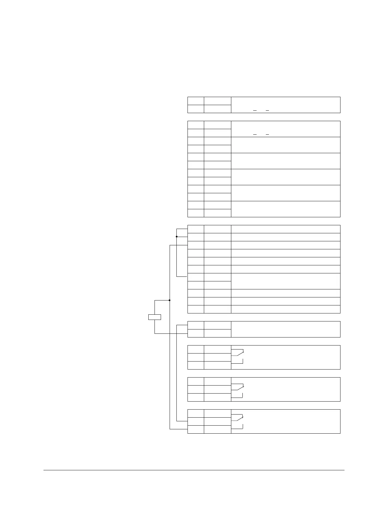
Connection diagram of the RMIO board in the line-side converter
Internal connections to the RMIO board for the ACS800 IGBT Supply Control
Program are shown below. Do not change the connections.
X20
1 VREF- Reference voltage -10 VDC,
1kohm<
R
L
< 10 kohm
2 GND
X21
1 VREF+ Reference voltage 10 VDC,
1kohm<
R
L
< 10 kohm
2GND
3 AI1+ By default, not in use. 0(2) ... 10 V,
R
in
>200kohm
4AI1-
5 AI2+ By default, not in use. 0(4) ... 20 mA,
R
in
= 100 ohm
6AI2-
7 AI3+ By default, not in use. 0(4) ... 20 mA,
R
in
= 100 ohm
8AI3-
9 AO1+ By default, not in use. 0(4)...20 mA,
R
in
= 100 ohm
10 AO1-
11 AO2+ By default, not in use. 0(4)...20 mA,
R
in
= 100 ohm
12 AO2-
X22
1 DI1 Acknowledgement of converter fan
1)
2 DI2 Stop/Start
3 DI3 Acknowledgement from main contactor
1)
4 DI4 By default not in use.
5 DI5 By default not in use.
6 DI6 Reset
1)
7 +24V +24 VDC max. 100 mA
8+24V
9 DGND Digital ground
10 DGND Digital ground
11 DI7(DIIL) By default not in use.
X23
1 +24V Auxiliary voltage output, non-isolated,
24 VDC 250 mA
2GND
X25
1 RO11 Relay output 1: Charging contactor
control
1)
2RO12
3RO13
X26
1 RO21 Relay output 2: fault (-1)
2RO22
3RO23
X27
1 RO31 Relay output 3: Main contactor
control
1)
2RO32
3RO33
1)
non-programmable I/O
K1
 Loading...

