1. The user pushes the emergency stop button (this activates the SS1 function of the FSO
module). The FSO module starts a timer for delay A.
2. The drive starts to decelerate the motor along the user-defined stop ramp (SAR1
parameter 200.112 SAR1 ramp time to zero).
3. b) The FSO module activates the drive STO and SBC functions (case B), opens the
main contactor/breaker and starts a counter for time D. The motor coasts to a stop.
4. b) The user releases the emergency stop button.
5. b) Time D has elapsed. The emergency stop indication lamp comes on. The user can
push the reset button, that is, the acknowledgement of the STO function is possible.
6. b) The user pushes the reset button (this resets the emergency stop circuit and
acknowledges the STO function).
7. b) The FSO module deactivates the STO function in the drive and closes the main
contactor/breaker. The emergency stop indication lamp goes off. The user must reset
the drive before it is ready for a restart (this is because the FSO module generates a
fault to the drive after a limit hit [parameter FSOGEN.62 STO indication safety limit]).
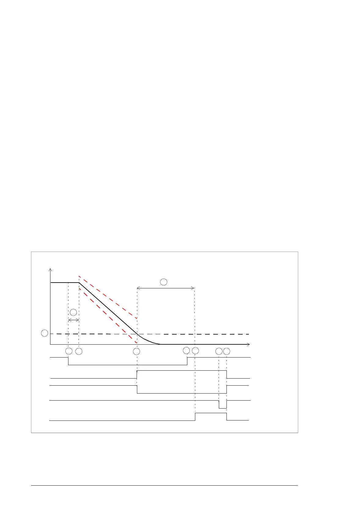
Emergency stop, stop category 1 with ramp monitoring
This time scheme diagram illustrates the operation of the Emergency stop, stop category
1 safety function with ramp monitoring. This option uses the Safe stop 1 (SS1) function of
the FSO module.
Case A: The motor speed reaches the zero speed limit within the user-defined stop ramp
monitoring window
Time
Motor speed
1
2
E-stop button
(SS1 request)
Drive STO
status
Reset button
B
3a
A
4a
Indication lamp
Contactor
(SBC output)
6a 7a
C
SBC.13
5a
Safety function response time.A
Zero speed limit: Speed limit for activating the drive STO and SBC functions. Activation of the
SBC function opens the main contactor/breaker. This is a user-defined value (parameter
FSOGEN.51 Zero speed without encoder).
B
24 Option description

 Loading...