5. b) The motor speed reaches the zero speed limit (B). The emergency stop indication
lamp comes on. The user can push the reset button, that is, the acknowledgement of
the STO function is possible.
6. b) The user pushes the reset button (this resets the emergency stop circuit and
acknowledges the STO function).
7. b) The FSO module deactivates the STO function in the drive and closes the main
contactor/breaker. The emergency stop indication lamp goes off. The user must reset
the drive before it is ready for a restart (this is because the FSO module generates a
fault to the drive after a limit hit [parameter FSOGEN.62 STO indication safety limit]).
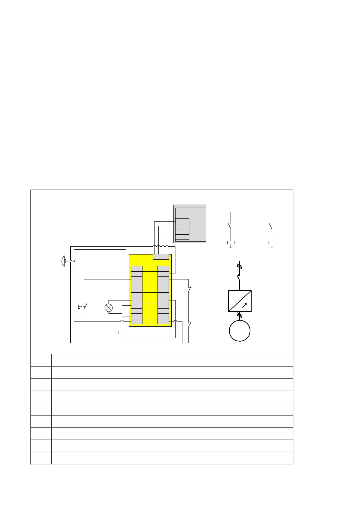
■ Operation principle diagrams
These diagrams are example circuit diagrams without the safety encoder interface.
Implementation of main contactor/breaker and charging circuit can vary depending on the
product. For a more detailed description, see the circuit diagrams delivered with the drive.
ACS880-07 drives, frames R6 to R11 and ACS880-17/-37 drives, frame R8
-Qx
Main circuit
M
3~
M
3~
~~
1)
~
-Qx
Main circuit
M
3~
~
1)
~
-S61
-A41
XSTO
IN2
OUT
SGND
IN1
IN2
OUT
SGND
IN1
-K62.1-K62.1
-K62.1
-Qx-Qx
-A68
4
1
2
3
8
5
6
7
10
9
4
1
2
3
8
5
6
7
10
9
4
1
2
3
8
5
6
7
10
9
4
1
2
3
8
5
6
7
10
9
DI
DO
GND
TP
X114 X113
-A68
4
1
2
3
8
5
6
7
10
9
4
1
2
3
8
5
6
7
10
9
DI
DO
GND
TP
X114 X113
X111
-A68
4
1
2
3
8
5
6
7
10
9
4
1
2
3
8
5
6
7
10
9
DI
DO
GND
TP
X114 X113
X111
-S62-S62
-K62.1-K62.1
-K21.1-K21.1
24 VDC+
-K62.1
-K21.1
24 VDC+
-K21.1-K21.1
-Qx-Qx
100-250 VAC
-K21.1
-Qx
100-250 VAC
Drive module1)
Inverter control unitA41
Safety functions module FSO-12/-21A68
Emergency stop buttonS61
Emergency stop reset button with indicator lightS62
Safety relayK21.1
Safety relayK62.1
Main contactor/breaker (Q2 or Q1)Qx
STO connections to inverter control unitX111
32 Option description

 Loading...