Planning the electrical installation
46
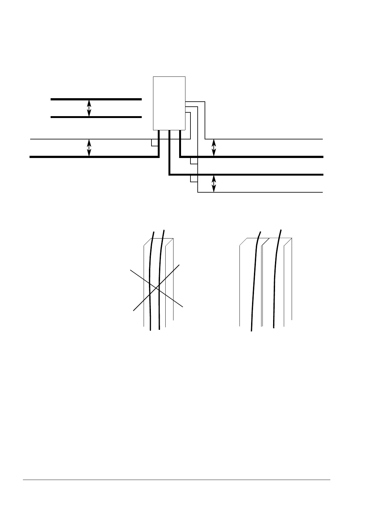
A diagram of the cable routing is below.
Control cable ducts
min 500 mm (20”)
Control cables
min 300 mm (12”)
Supply cable
Motor cable
Motor cable
min 500 mm (20”)
Braking resistor cable
90°
90°
Drive
90°
min 200 mm (20”)
Supply cable
230 V24 V24 V 230 V
Lead 24 V and 230 V control
cables in separate ducts inside
the cabinet.
Not allowed unless the 24 V
cable is insulated for 230 V or
insulated with an insulation
sleeving for 230 V.
 Loading...


