Electrical installation
61
Drive-to-drive link (X5)
The drive-to-drive link is a daisy-chained RS-485 transmission line that allows basic
master/follower communication with one master drive and multiple followers.
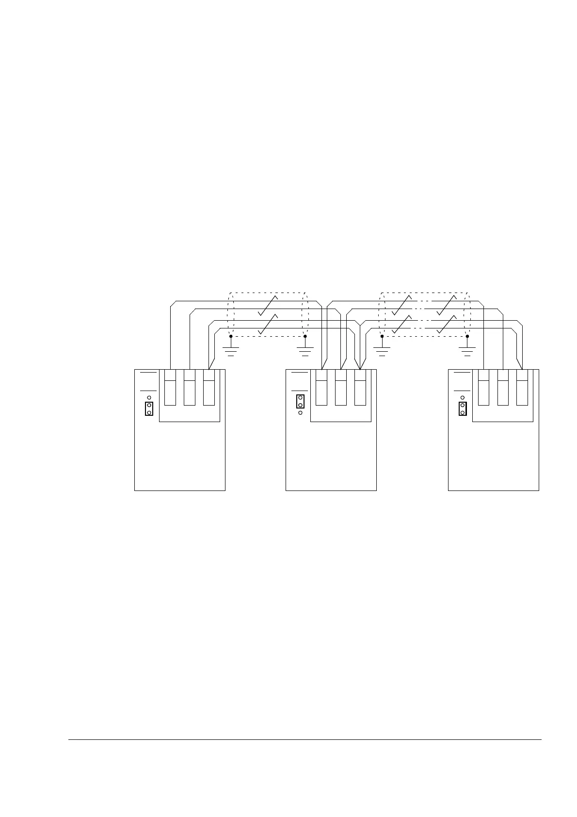
Termination activation jumper J3 (see section Jumpers above) next to this terminal
block must be set to the ON position on the drives at the ends of the drive-to-drive
link. On intermediate drives, the jumper must be set to the OFF position.
Shielded twisted-pair cable (~100 ohm, e.g. PROFIBUS-compatible cable) must be
used for the wiring. For best immunity, high quality cable is recommended. The cable
should be kept as short as possible; the maximum length of the link is 50 metres
(164 ft). Unnecessary loops and running the cable near power cables (such as motor
cables) must be avoided. The cable shields are to be grounded to the control cable
clamp plate on the drive as shown on page 62.
The following diagram shows the wiring of the drive-to-drive link.
Safe Torque Off (X6)
For the drive to start, both connections (OUT1 to IN1, and OUT2 to IN2) must be
closed. By default, the terminal block has jumpers to close the circuit. Remove the
jumpers before connecting an external Safe Torque Off circuitry to the drive. See
page 41.
X5:D2D
...
1
T
J3
Termination ON
JCU
Drive 1
B
2
A
3BGND
X5:D2D
1
J3
Termination OFF
JCU
Drive 2
B
2A
3
BGND
T
X5:D2D
1
T
J3
Termination ON
JCU
Drive n
B
2A
3
BGND
 Loading...


