Resistor braking
85
Resistor installation and wiring
All resistors must be installed outside the drive module in a place where they are
cooled sufficiently, do not block the airflow to other equipment, or dissipate hot air
into the air inlets of other equipment.
WARNING! The materials near the braking resistor must be non-flammable. The
surface temperature of the resistor may rise above 200 °C (400 °F), and the
temperature of the air flowing from the resistor is hundreds of degrees Celsius.
Protect the resistor against contact.
The maximum length of the resistor cable(s) is 20 m (65 ft). For the connections, see
section Power cable connection on page 54.
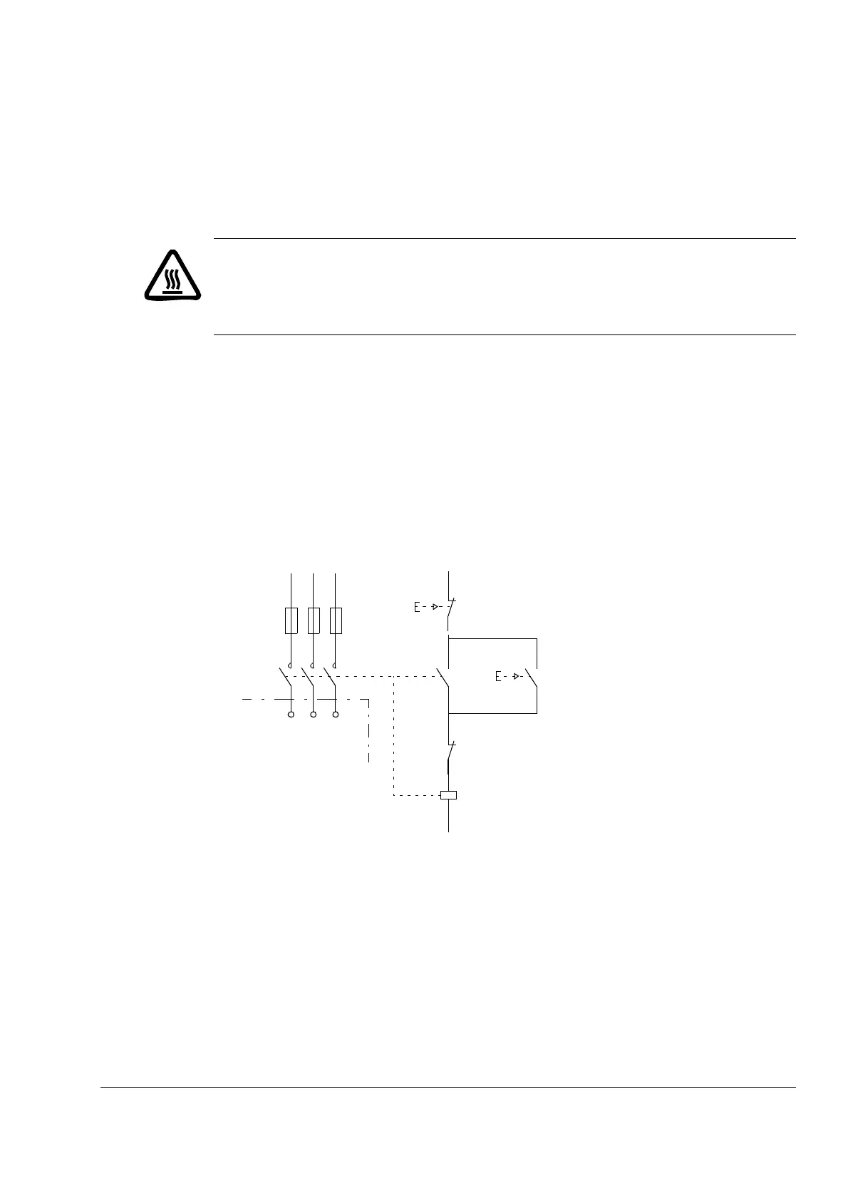
Contactor protection of drive
It is highly recommended to equip the drive with a main contactor for safety reasons.
Wire the contactor so that it opens in case the resistor overheats. This is essential
for safety since the drive will not otherwise be able to interrupt the main supply if the
chopper remains conductive in a fault situation.
Below is a simple example wiring diagram.
ACSM1
U1 V1 W1
L1 L2 L3
1
2
3
4
5
6
13
14
3
4
1
2
K1
Θ
Fuses
OFF
ON
Resistor thermal switch
 Loading...


